Optidrive P2 Advanced User Guide Rev 2.00
Optidrive P2 Parameter Set Overview
Deceleration Ramp Select Bit 0 Logic Source
Deceleration Ramp Select Bit 1 Logic Source
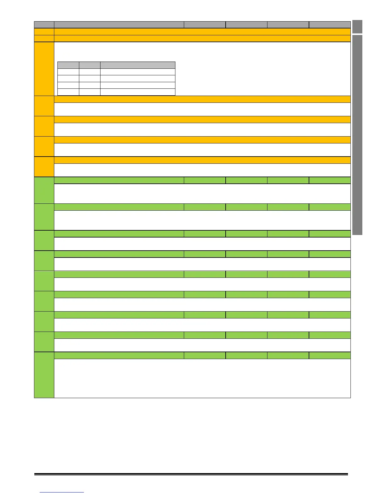
These parameters allow alternative deceleration ramp times to be selected based on the status of the parameters above. In order to
use the function, P8-13 must be 0 (default setting), otherwise the ramps are automatically selected based on output frequency. The
acceleration ramp time is selected according to the following logic :-
Deceleration Ramp Parameter
Remote (Keypad) Up Input Logic Source
Defines the source of the logic signal used to increase the value of the Keypad / Motorised Pot speed reference. When the defined
signal source is Logic 1, the value will increase at the rate defined by P1-03.
Remote (Keypad) Down Input Logic Source
Defines the source of the logic signal used to decrease the value of the Keypad / Motorised Pot speed reference. When the defined
signal source is Logic 1, the value will decrease at the rate defined by P1-04.
Speed Limit Switch Forward Input Logic Source
Defines the source of the logic signal used to act as a forward speed limit switch. Once enabled, if the input signal source is logic 0 and
the speed reference is greater than 0, the drive will Fast Stop.
Speed Limit Switch Reverse Input Logic Source
Defines the source of the logic signal used to act as a reverse speed limit switch. Once enabled, if the input signal source is logic 0 and
the speed reference is less than 0, the drive will Fast Stop.
Analog Output 1 Data Source Enable
0 : Analog Output 1 Function Set by P2-11
1 : Analog Output 1 Function Set by User Defined Digital Source
2 : Analog Output 1 Function set by User Defined Analog Source
Analog Output 2 Data Source Enable
0 : Analog Output 1 Function Set by P2-13
1 : Analog Output 1 Function Set by User Defined Digital Source
2 : Analog Output 1 Function set by User Defined Analog Source
Relay Output 1 Logic Source Enable
0 : Relay Output 1 Function Set by P2-15
1 : Relay Output 1 Function set by User Defined Source
Relay Output 2 Logic Source Enable
0 : Relay Output 1 Function Set by P2-18
1 : Relay Output 1 Function set by User Defined Source
Scaling Control Data Source Enable
0 : Scaling Control Data Source Set by P2-21
1 : Scaling Control by User Defined Source
PID Setpoint Data Source Enable
0 : PID Setpoint Source Defined by P3-05
1 : PID Setpoint Source set by User Defined Source
PID Feedback Data Source Enable
0 : PID Feedback Source Defined by P3-10
1 : PID Feedback Source set by User Defined Source
Torque Reference Data Source Enable
0 : Torque Reference / Limit Source Set by P4-06
1 : Torque Reference User Defined Source
Relay Output Option Module Logic Source Enable
0 : Option Module Output Relays Factory Preset Functions Assigned
Factory Preset Functions are as follows :-
Relay 3 (Extended I/O & Cascade Option Module) : Drive Healthy
Relay 4 (Cascade Option Module) : Drive Tripped
Relay 5 (Cascade Option Module) : Drive Running
1 : Relay Output 1 Function set by User Defined Source