Optidrive VTC – User Guide
30 www.invertek.co.uk
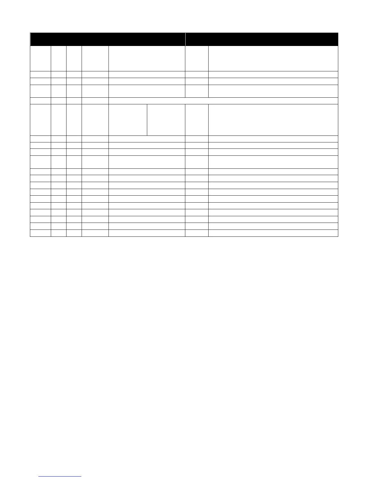
10.5. Modbus Register Map
16 Bit Word.
Bit 0 : Low = Stop, High = Run Enable
Bit 1 : Low = No Function, High = Fault Reset
Bit 2 : Low = Decel Ramp 1 (P1-04), High = Decel Ramp 2
Modbus Speed reference setpoint
Setpoint frequency x10, e.g. 100 = 10.0Hz
Acceleration and Deceleration
Time
Ramp time in seconds x 10, e.g. 250 = 25 seconds
Low Byte = Drive Error Code, see table below
High Byte = Drive Status as follows :-
0 : Drive Stopped
1: Drive Running
2: Drive Tripped
Output frequency in Hz x10, e.g. 100 = 10.0Hz
Output Motor Current in Amps x10, e.g. 10 = 1.0 Amps
Output Motor Power in kW x10, e.g. 100 = 10.0kW
Indicates the status of the 4 digital inputs
Lowest Bit = 1 Input 1
Bipolar analog input value
Analog input % of full scale x10, e.g. 1000 = 100%
Analog input % of full scale x10, e.g. 1000 = 100%
Drive heatsink temperature in ºC
Further registers are available; see the Advanced User Guide for details.