Wiring
18
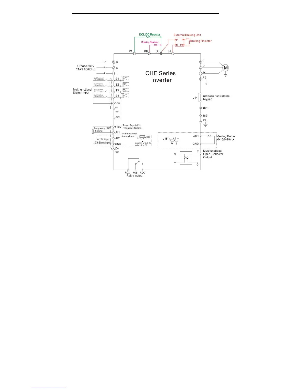
4.3 Typical Wiring Diagram
Figure4. 12 Wiring diagram.
Notice
1. Inverters between 18.5KW and 90KW have built-in DC reactor which is used to
improve power factor. For inverters above 110KW, it is recommended to install DC
reactor between P1 and (+).
2. Inverters below 15KW have built-in braking unit. If need braking, only need to
install braking resistor between PB and (+).
3. For inverters above 18.5KW, if need braking, should install external braking
unit between (+) and (-).
 Loading...

