Detailed Function Description
77
10: ASCII, 1 start bit, 7 data bits, even parity check, 2 stop bits.
11: ASCII, 1 start bit, 7 data bits, odd parity check, 2 stop bits.
12: ASCII, 1 start bit, 8 data bits, no parity check, 1 stop bit.
13: ASCII, 1 start bit, 8 data bits, even parity check, 1 stop bit.
14: ASCII, 1 start bit, 8 data bits, odd parity check, 1 stop bit.
15: ASCII, 1 start bit, 8 data bits, no parity check, 2 stop bits.
16: ASCII, 1 start bit, 8 data bits, even parity check, 2 stop bits.
17: ASCII, 1 start bit, 8 data bits, odd parity check, 2 stop bits.
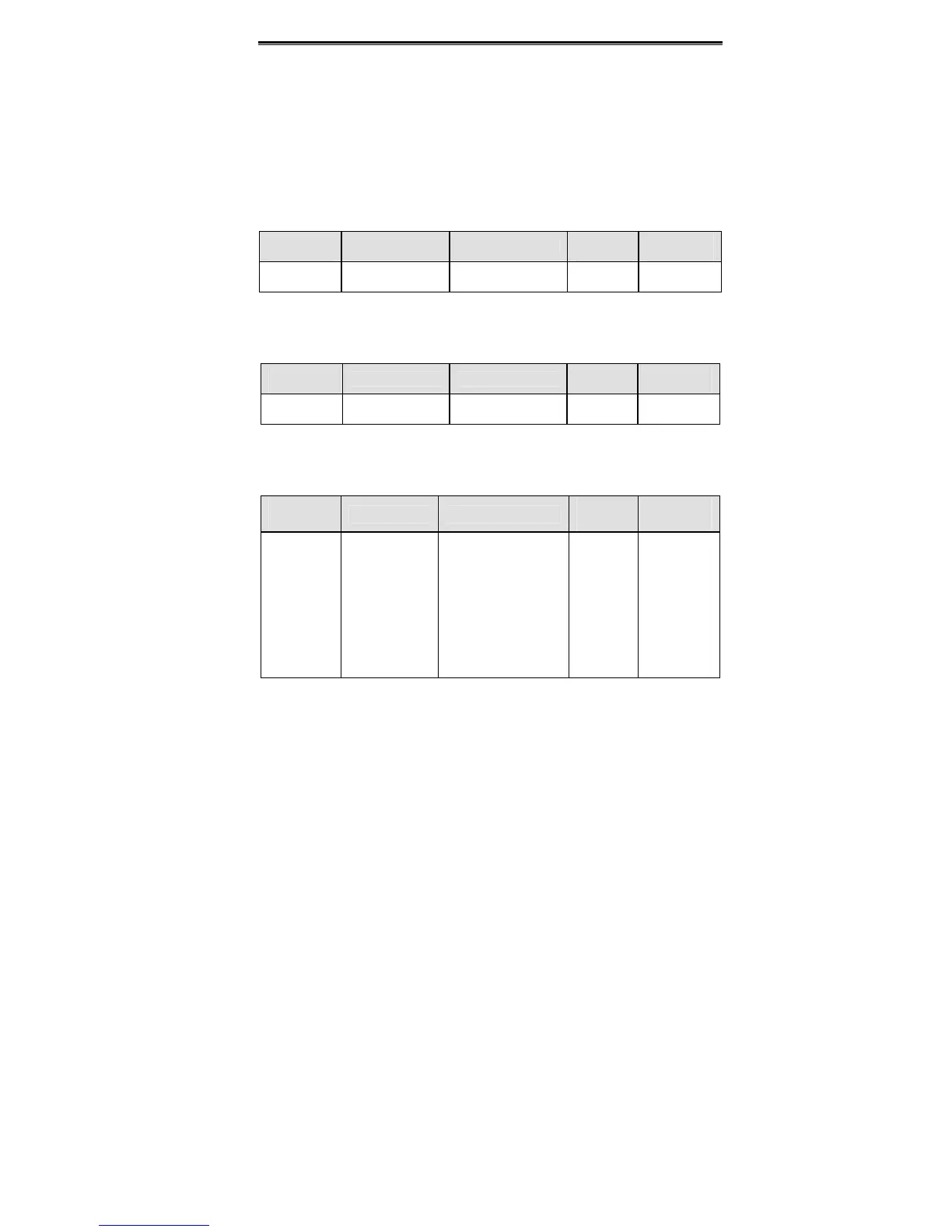
Function
Code
Name Description
Setting
range
Factory
Setting
PC.03
Communication
delay time
0~200ms 0~200 5ms
This parameter can be used to set the response delay in communication in
order to adapt to the MODBUS master. In RTU mode, the actual communication delay
should be no less than 3.5 characters’ interval; in ASCII mode, 1ms.
Function
Code
Name Description
Setting
Range
Factory
Setting
PC.04
Communication
timeout delay
0.0: Disabled
0.1~100.0s
0~100.0 0.0s
When the value is zero, this function will be disabled. When communication interruption is
longer than the non-zero value of PC.04, the inverter will alarm communication error
(CE).
Function
Code
Name Description
Setting
Range
Factory
Setting
PC.05
Communication
error action
0: Alarm and coast to
stop
1: No alarm and
continue to run
2: No alarm but stop
according to P1.05 (if
P0.01=2)
3: No alarm but stop
according to P1.05
0~3 1
0: When communication error occurs, inverter will alarm (CE) and coast to stop.
1: When communication error occurs, inverter will omit the error and continue to run.
2: When communication error occurs, if P0.01=2, inverter will not alarm but stop
according to stop mode determined by P1.05. Otherwise it will omit the error.
3: When communication error occurs, inverter will not alarm but stop according to stop

 Loading...