KEYPAD INTRODUCTION
No. Name Description
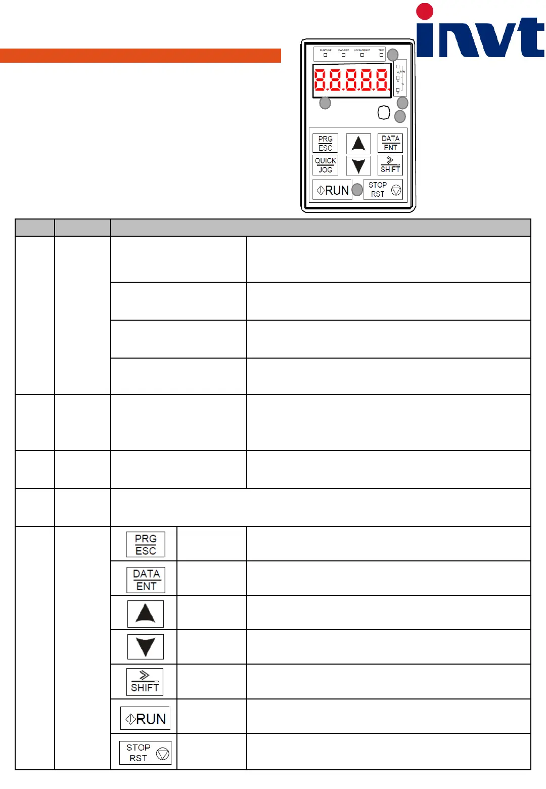
1
Status
indicator
RUN/TUNE
Running status indicator.
LED off means that inverter is in the stopping state; LED blinking means the
inverter is in the parameter auto tuning sate; LED on means the inverter is in the
running state.
FWD/REV
FED/REV indicator.
LED off means the inverter is in the forward rotation state; LED on means the
inverter in in the reverse rotation state.
LOCAL/REMOTE
LED for keypad operation, terminals operation and remote communication
control; LED off means that the inverter is in the keypad operation state; LED
blinking means the inverter is in the remote communication control state.
TRIP
Fault indicator.
LED on when the inverter is in the fault state; LED off in normal state; LED blinking
means the inverter is in the overload pre-alarm state.
2
Unit
Indicator
Indicating the unit of the displayed
digits
Hz – Unit of frequency
A – Unit of current
V – Unit of voltage
RPM – Unit of rotating speed
% – Percentage
3
Code
displaying
zone
displaying zone
5-digit LED display , displaying various monitoring data and alarm code such as set
frequency and output frequency
4
Analog
potentiomet
er
Corresponds to AI1.
5 Buttons
Programming
key
Enter or escape from the first level menu and remove the parameter quickly
Entry key
Enter the menu step-by-step confirm parameters
Up key
Increase data or function code progressively
Down key
Decrease data or function code progressively
Right-shift key
Move right to select the displaying parameter circularly in stopping and running
mode. Select the parameter modifying digit during the parameter modification.
Run key
This key is used to run the inverter in key operation mode.
Stop /Reset key
This key is used to stop the inverter when it is in running state, and is limited by
function code PO07.04
This key is used to reset all control modes in
1
23
4
5