GD200A series VFD Product overview
-7-
3 Product overview
3.1 What this chapter contains
The chapter briefly describes the operation principle, product characteristics, layout, nameplate and
type designation information.
3.2 Basic principles
Goodrive200A series VFDs are wall, flange and floor mountable devices for controlling
asynchronous AC inductance motors.
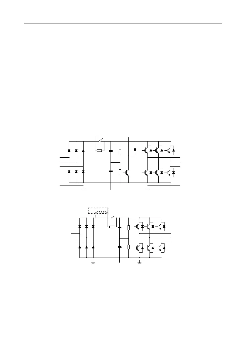
The diagram below shows the main circuit diagram of the VFD. The rectifier converts three-phase
AC voltage to DC voltage. The capacitor bank of the intermediate circuit stabilizes the DC voltage.
The converter transforms the DC voltage back to AC voltage for the AC motor. The brake pipe
connects the external braking resistor to the intermediate DC circuit to consume the feedback
energy when the voltage in the circuit exceeds its maximum limit.
Figure 3-1 Main circuit diagram (for the 030G/037P and lower models)
R
S
T
U
V
W
(+)
(-)
DC reactor
P1
PE PE
Figure 3-2 Main circuit diagram (for the 037G/045P and higher models)
Note:
1. The 037G/045P and higher models support external optional DC reactors. Before connecting, it is
necessary to remove the copper strip between P1 and (+).
2. The 030G/037P and lower models have standard embedded braking units and the braking
resistor is optional.

 Loading...


