GD200A series VFD Keypad operation procedure
-28-
5 Keypad operation procedure
5.1 What this chapter contains
This chapter contains following operation:
Buttons, indicating lights and the screen as well as the methods to inspect, modify and set
function codes by keypad
Start
5.2 Keypad
The keypad is used to control Goodrive200A series VFDs, read the state data and adjust
parameters.
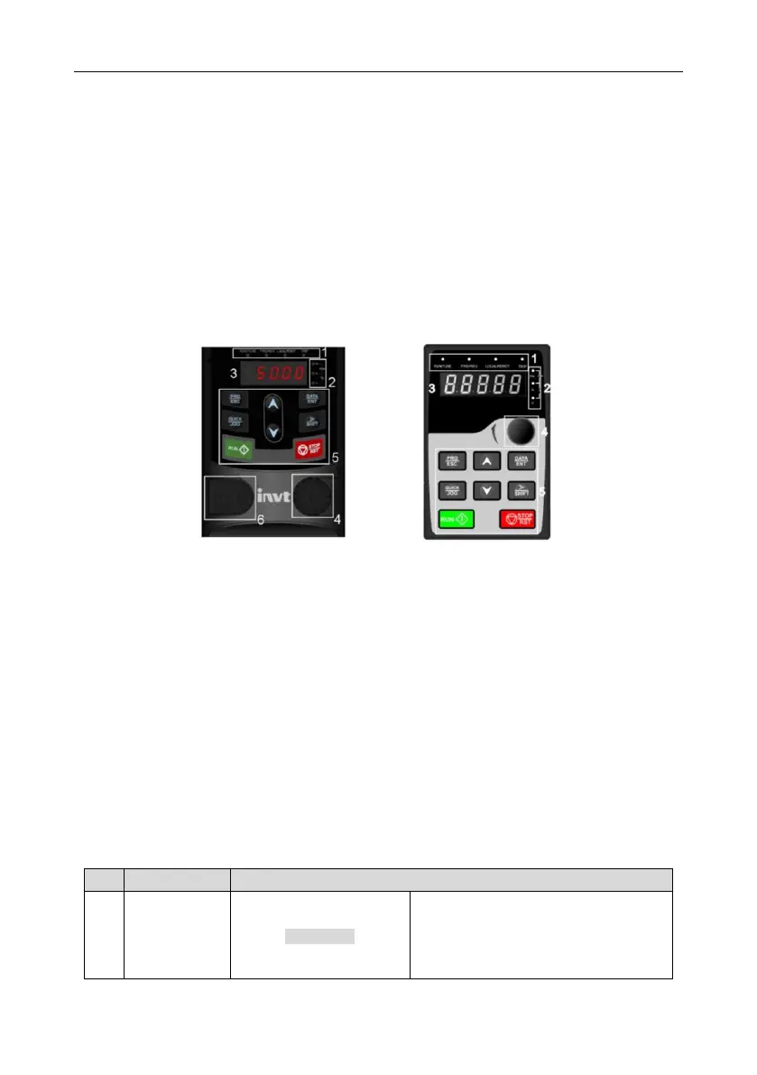
A B
Figure 5-1 Keypad
Note:
A in Figure 5-1 shows the keypad of the 0R7G–015G/018P models and B in Figure 5-1 shows
that of the 018G/022P–500G models.
The 0R7G–015G/018P models support optional LED keypads and all series support optional
LCD keypads. The LCD keypad supports several languages, parameters copy, high-definition
display and its installation dimension is compatible with the LED.
Use strew or installation bracket to fix the external keypad. If you need to use the keypad in
another place rather than on the VFD, use a network cable with a standard RJ45 crystal head
as the extension cable. The keypad installation brackets are optional for the 0R7G–030G/037P
models, while keypad installation brackets are standard configuration for the
037G/045P–500G models.
LED off – the VFD is stopped
LED blinking – the VFD is in parameter
autotune
LED on – the VFD is running

 Loading...


