GD200A series VFD Installation guidelines
-26-
S1
S2
COM
PW
+24V
COM
+24V
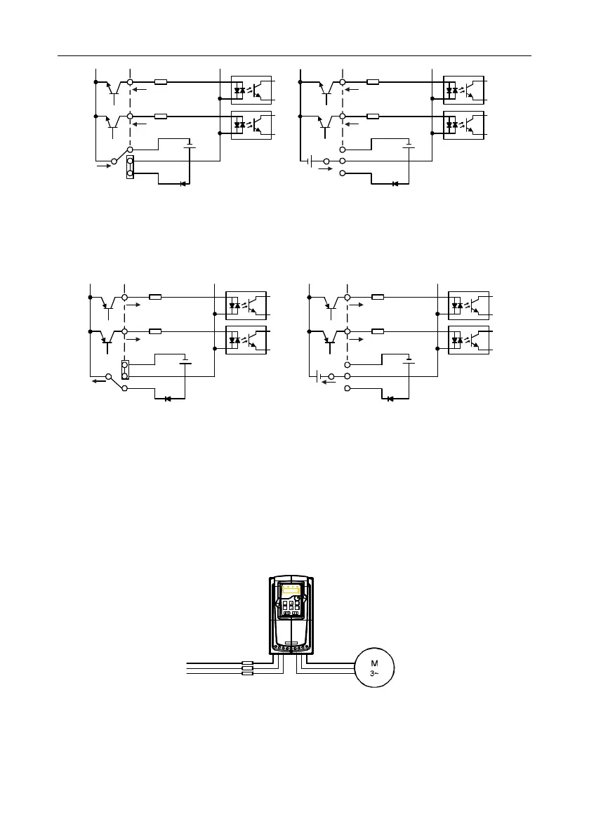
Internal power supply (NPN)
S1
S2
COM
PW
+24V
COM
+24V
External power supply (NPN)
+24V
Figure 4-23 NPN modes
If the signal is from PNP transistor, please set the U-shaped contact tag as below according to the
used power supply.
S1
S2
COM
PW
+24V
COM
+24V
External power supply (PNP)
S1
S2
COM
PW
+24V
COM
+24V
Internal power supply (PNP)
Figure 4-24 PNP modes
4.4 Layout protection
4.4.1 Protecting the VFD and input power cable in short-circuit situations
Protect the VFD and input power cable in short circuit situations and against thermal overload.
Arrange the protection according to the following guidelines.
Figure 4-25 Fuse configuration
Note: Select the fuse as the manual indicated. The fuse will protect the input power cable from
damage in short-circuit situations. It will protect the surrounding devices when the internal of the
VFD is short circuited.

 Loading...


