GD200A series VFD Installation guidelines
-15-
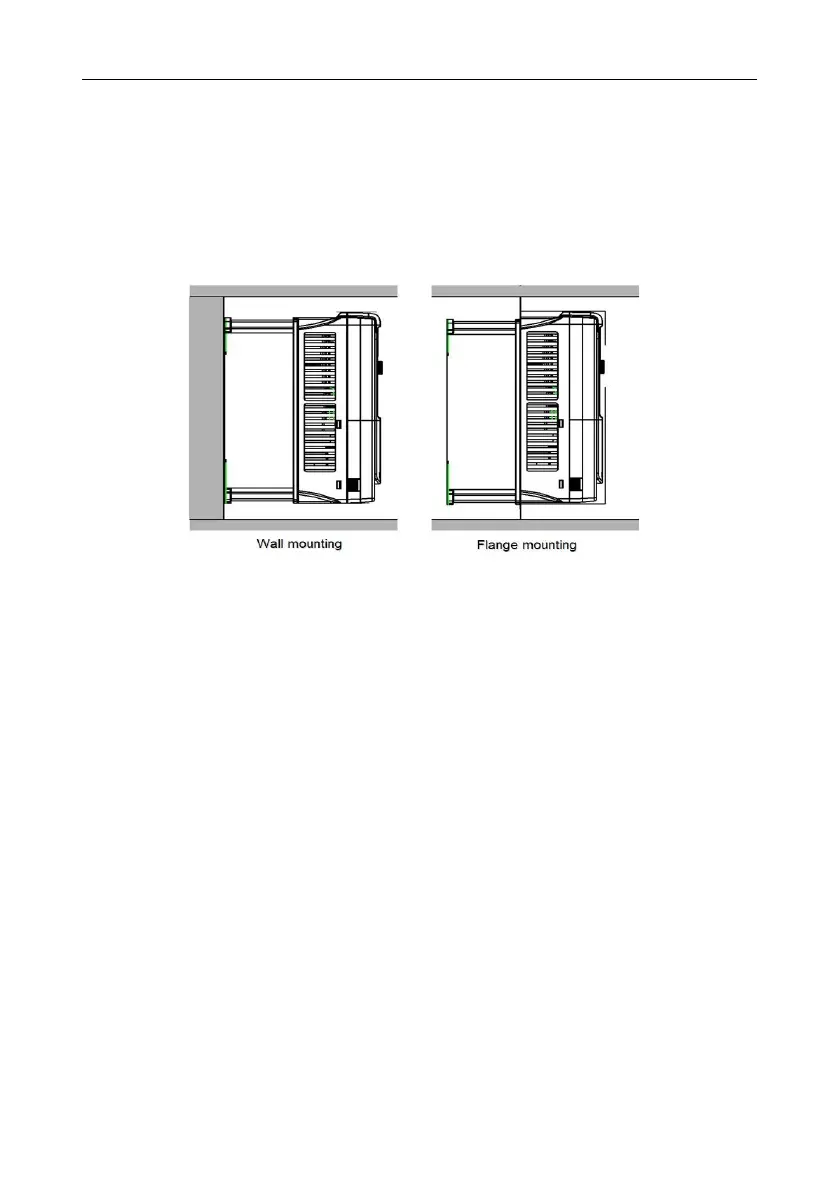
4.2.3 Installation manner
The VFD can be installed in two different ways, depending on the frame size:
a) Wall mounting (for the 315G/355P and lower models)
b) Flange mounting (for the 200G/220P and lower models). Some need optional flange installation
board.
c) Floor mounting (for the 220G/250P–500G models). Some need optional base.
Figure 4-2 Installation manner
(1) Mark the hole location. The location of the holes is shown in the dimension drawings in the
appendix.
(2) Fix the screws or bolts to the marked locations.
(3) Position the drive onto the wall.
(4) Tighten the screws in the wall securely.
Note:
The flange installation bracket is needed in the flange installation of the 0R7G–030G/037P
models while the flange installation of the 037G/045P–200G/220P models does not need the
installation bracket.
The 220G/250P–315G/355P models need optional base in the floor installation.
4.2.4 Multiple installations
Parallel installation

 Loading...


