GD200A series VFD Peripheral options and parts
-172-
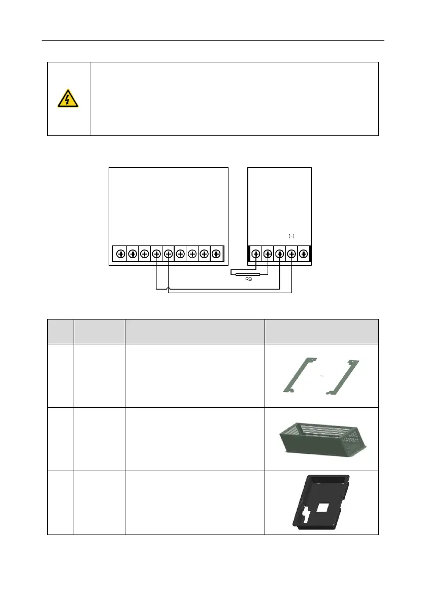
Installation of braking units:
The 037G/045P and higher models only need external braking units.
(+), (-) are the wiring terminals of the braking units.
The wiring length between the (+),(-) terminals of the VFD and the (+),(-)
terminals of the braking units should be no more than 5m,and the distributing
length among BR1 and BR2 and the braking resistor terminals should be no
more than 10m.
Signal installation is as below:
DBU
(+)
DC+
(-)
DC-
PB (+) (+) PE
C.9 Other optional parts
Flange
installation
bracket
Needed for the flange installation of the
0R7G–030G/037P models
Not needed for the flange installation of
the 037G/045P–200G/220P models
Optimal for the 220G/250P–315G/355P
models
An input AC/DC reactor and output AC
reactor can be put in the base.
Use the screw or installation bracket to
fix the external keypad.
Optional for the 0R7G–030G/037P
models and standard for the
037G/045P–500G models

 Loading...


