GD200A series VFD Keypad operation procedure
-29-
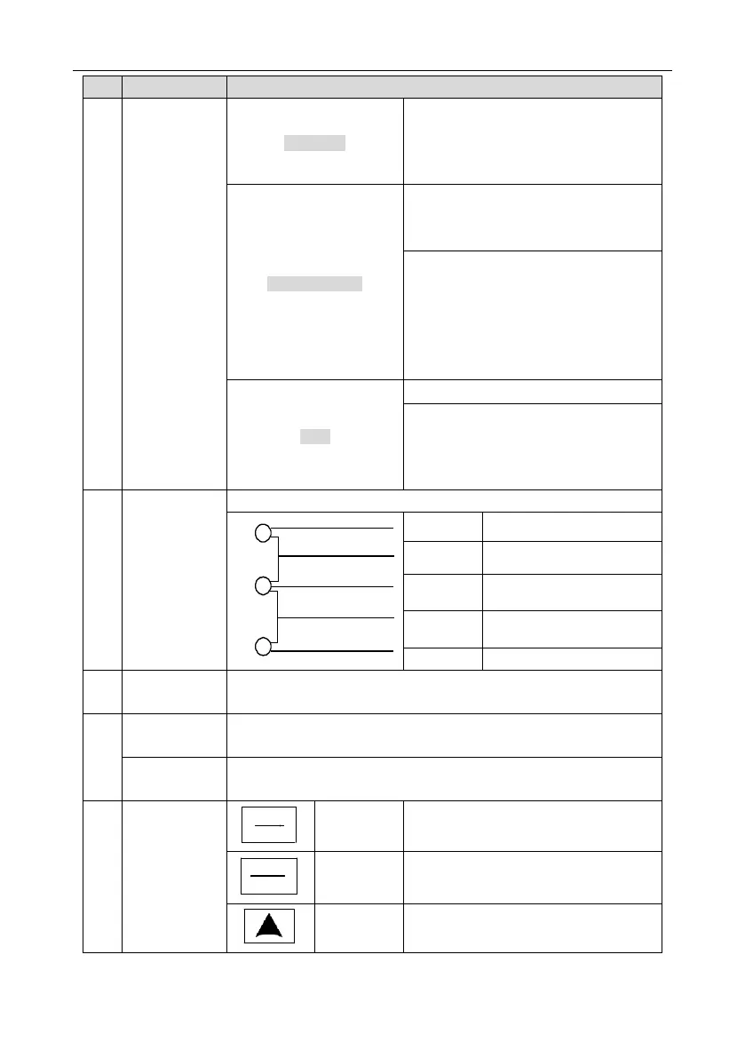
LED off – the VFD will run in the forward
direction
LED on – the VFD will run in the reverse
direction
LED indicates keypad operation, terminal
operation and remote communication
control
LED off – the VFD is in keypad operation
mode
LED blinking – the VFD is in terminal
operation mode
LED on – the VFD is in remote operation
control mode
LED for faults
LED on – the VFD is faulty
LED off – normal state
LED blinking – the VFD is in pre-alarm, and
will trip soon without corrective actions
Mean the unit displayed currently
5-figure LED display displays various monitoring data and alarm code
such as set frequency and output frequency.
Equal to AI1.
A pplicable to the 015G/018P and lower models.
Tuning frequency. Please refer to P08.42.
Applicable to the 018G/022P and higher models.
Enter or escape from the first level menu
and delete shortcut parameter
Enter the menu step-by-step
Confirm parameters
Increase data or function code
progressively

 Loading...


