GD200A series VFD Function parameters
-77-
Setting range of P08.35: 0.0–100.0%
(FDT2 electrical level)
Amplitude
value for
frequency
arrival
detection
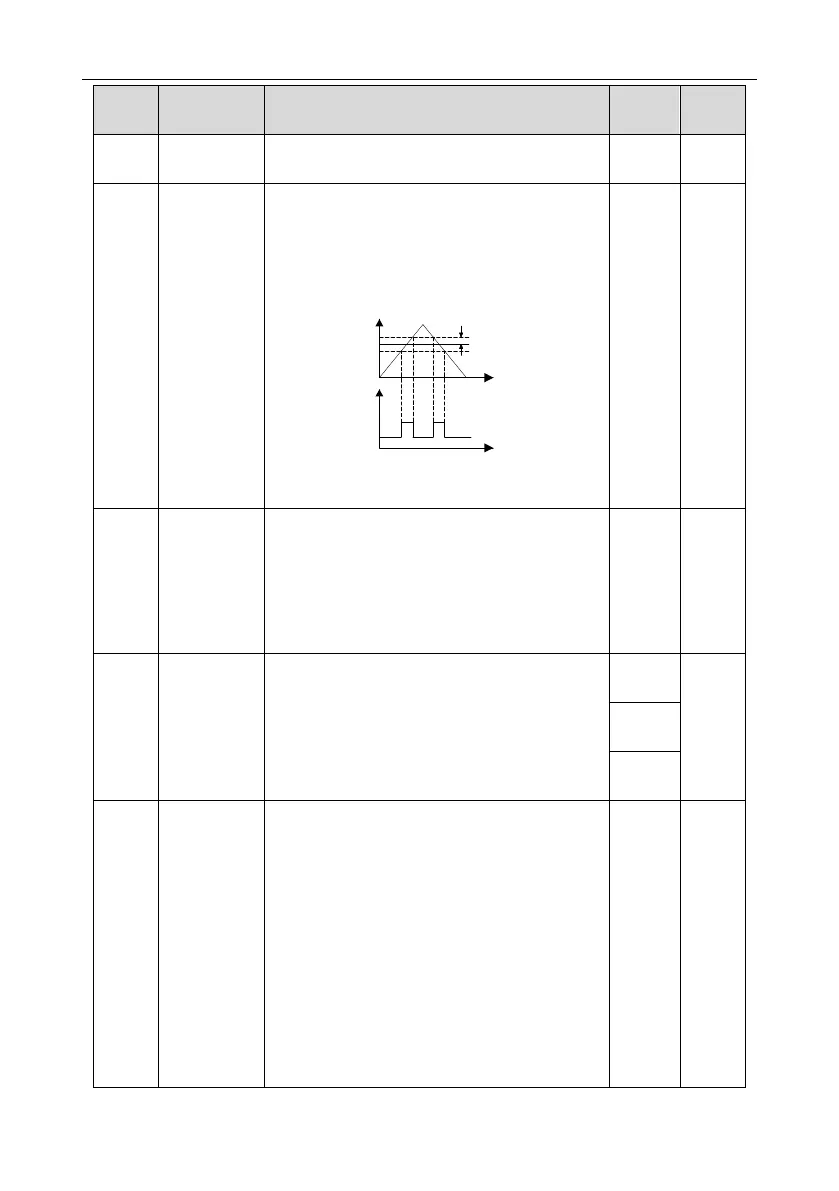
When the output frequency is among the below or
above range of the set frequency, the
multi-function digital output terminal will output the
signal of "frequency arrival", see the diagram
below for detailed information:
Y
RO1, RO2
,
Output frequency
Detecting range
T
T
The setting range: 0.00Hz–P00.03
(the max. frequency)
This parameter is used to control the internal
braking unit.
0: Disable
1: Enable
Note: Only applicable to the models with internal
braking units.
After setting the original bus voltage, adjust this
parameter to break the load appropriately. The
factory value changes with voltage level.
Setting range: 200.0–2000.0V
Set the operation mode of the cooling fan.
0: Normal mode, after the rectifier receives
operation command or the detected temperature
of module is above 45°C or the module current is
above 20% of the rated current, the fan rotates.
1: The fan keeps on running after power on
(generally for the site with high temperature and
humidity)
2: The fan will start when the ramp frequency of
the VFD is larger than 0Hz; if the running
frequency is 0Hz or changes from running state to
stop state, the fan will stop after one minute.
Setting range: 0–2

 Loading...


