Goodrive350-19 series VFD Commissioning
- 95 -
(+) PB
GD350-19 VFD
R
S
T
R
S
T
M
3~
U
V
W
PG
PE
PWR
PGND
A1+
A1-
B1+
B1-
Z1+
Z1-
S1
S2
S3
S4
HDIA
HDIB
S5
S6
COM
Brake
output
VFD fault
output
Brake failure
output
Brake check
reminding/
Overload
reminding
RO1A
RO1B
RO1C
RO2A
RO2B
RO2C
Y1
CME
HDO
COM
CME
+24V
Lifting
Lowering
Graded reference terminal 1
Graded reference terminal 2
Graded reference terminal 3
Graded reference terminal 4
Fault reset
Brake feedback
Braking resistor
S7
S8
Upward limit position
Downward limit position
PW
+24V
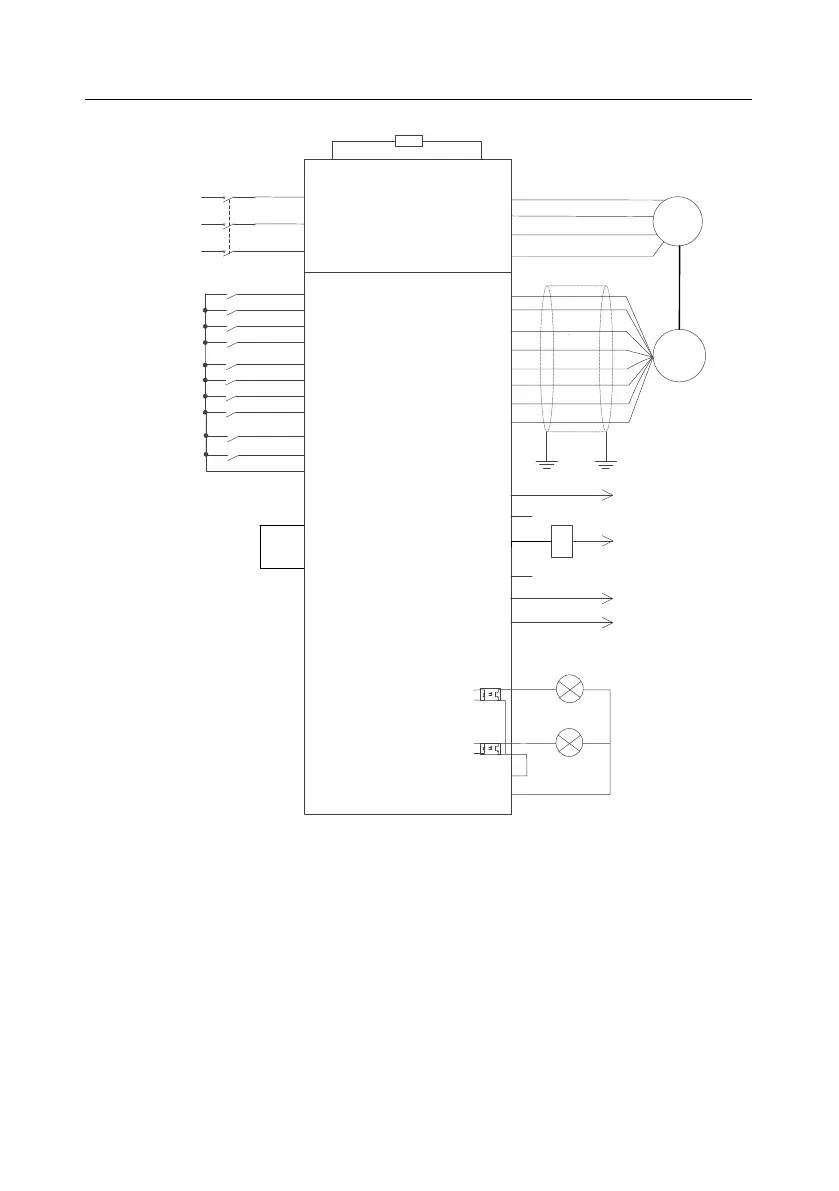
Figure 5.15 Wiring for internal measuring (motor encoder)
According to figure 5.15, you need to set the suspension ratio P93.10 when pulleys are used, so that
the height can be correctly measured in the closed-loop mode. Then the measured encoder pulse
count is used to calculate the actual running distance of the motor. During the first running, the upper
limit needs to be calibrated. You need to use a PG card to connect the encoder (see Appendix A.6 for
specific connection method), set P00.00=3 (Closed-loop control mode), P93.08=1 to enable internal
measuring (motor encoder), and then set winding drum and cable parameters such as P93.09,
P93.10, P93.11, P93.12, P93.13, P93.14 and P93.15.
The procedure for first running is as follows:

 Loading...

