Goodrive350-19 series VFD Operating
- 193 -
P22.14 (spindle drive ratio) to 1. As the encoder is not installed on the motor, the control performance
of closed-loop vector will be affected.
Proximity switch positioning supports the following spindle positioning modes:
a) The encoder is installed on the motor shaft, the drive ratio between motor shaft and spindle is
not necessarily 1:1;
At this point, it is required to set P22.14 (spindle drive ratio).
5. Commissioning procedures for digital positioning
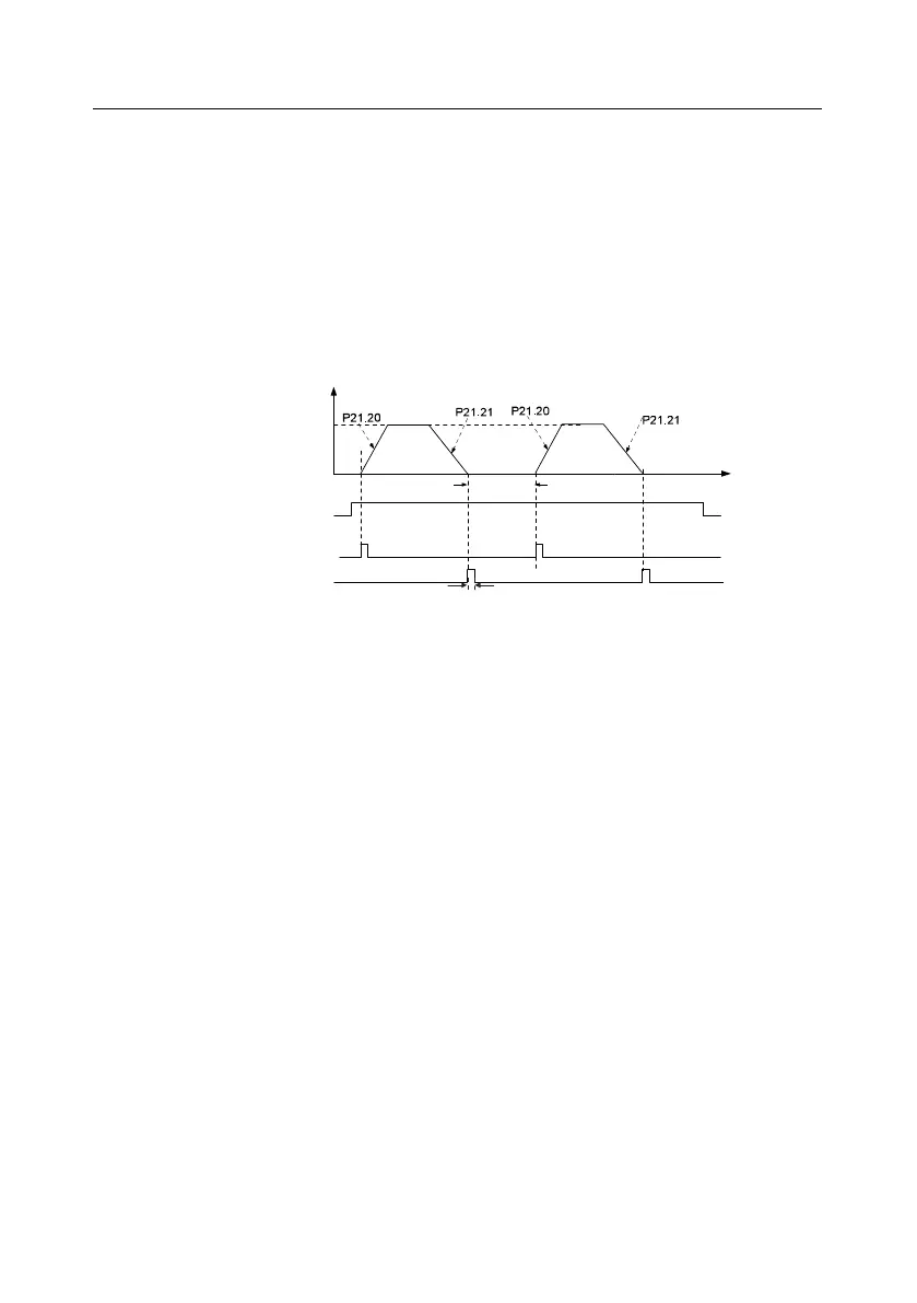
The diagram for digital positioning is shown below.
Frequency
Positioning
speed
Running command
Cyclic positioning
enable signal terminal
Positioning completion signal
P21.22 Hold time
of positioning arrival
Time
P21.25 Hold time of positioning completion signal
Step 1–4: These four steps are the Same as the first four steps of the commissioning procedures for
closed-loop vector control, which aim to fulfill the control requirements of closed-loop vector control.
Step 5: Set P21.00=0011 to enable digital positioning. Set P21.17, P21.11 and P21.12 (set positioning
displacement) according to actual needs ; set P21.18 and P21.19 (set positioning speed); set P21.20
and P21.21 (set acceleration/deceleration time of positioning).
Step 6: Single positioning operation
Set P21.16.bit1=0, and the motor will carry out single positioning action and stay in the positioning
position according to the setup in step 5.
Step 7: Cyclic positioning operation
Set P21.16.bit1=1 to enable cyclic positioning. The cyclic positioning is divided into continuous mode
and repetitive mode; you can also carry out cyclic positioning through terminal function (no. 55,
enable digital positioning cycle)
6. Commissioning procedures for positioning of photoelectric switch
Photoelectric switch positioning is to realize positioning function based on closed-loop vector control.

 Loading...

