Goodrive350-19 series VFD Installing
- 21 -
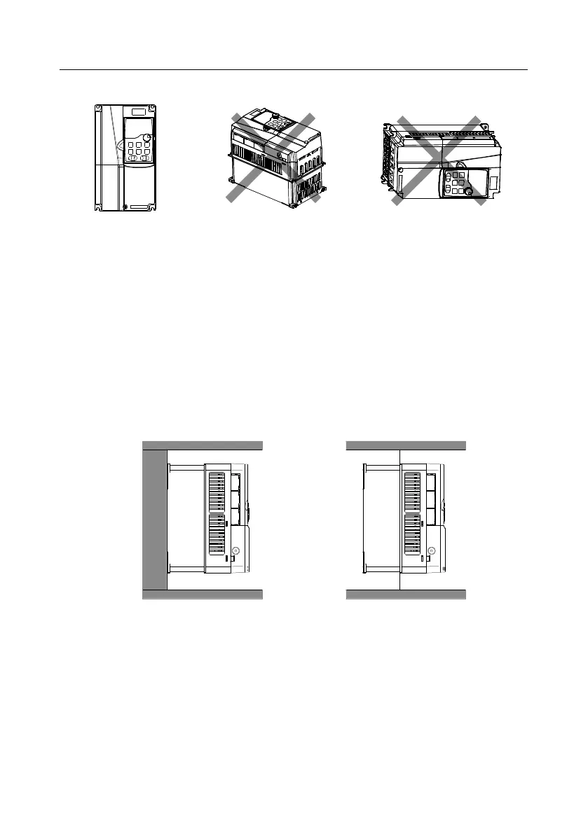
NG
b. Horizontal installation c. Lateral installation
OK
NG
a. Vertical installation
Figure 4.1 VFD installation direction
4.2.3 Installation methods
There are three installation methods by VFD outline dimensions:
Wall mounting: applicable to the 380V 315kW and lower VFD models and the 660V 355kW and
lower models.
Flange mounting: applicable to the 380V 200kW and lower VFD models and the 660V 220kW
and lower VFD models.
Floor mounting: applicable to the 380V 220–500kW VFD models and the 660V 250–630kW VFD
models.
Wall mounting
Flange mounting
Figure 4.2 Installation methods
Step 1 Mark the positions of the installation holes. For details about the positions, see the VFD outline
dimension drawings in Appendix C.
Step 2 Mount the screws or bolts onto the marked positions.
Step 3 Place the VFD against the wall.
Step 4 Fasten the screws on the wall.

 Loading...

