Goodrive350-19 series VFD Extension cards
-463-
the extension card network interface and upper
computer network interface is successful, but
there is no interaction between the extension
card and upper computer.
This indicator is on after the control board feeds
power to the communication card.
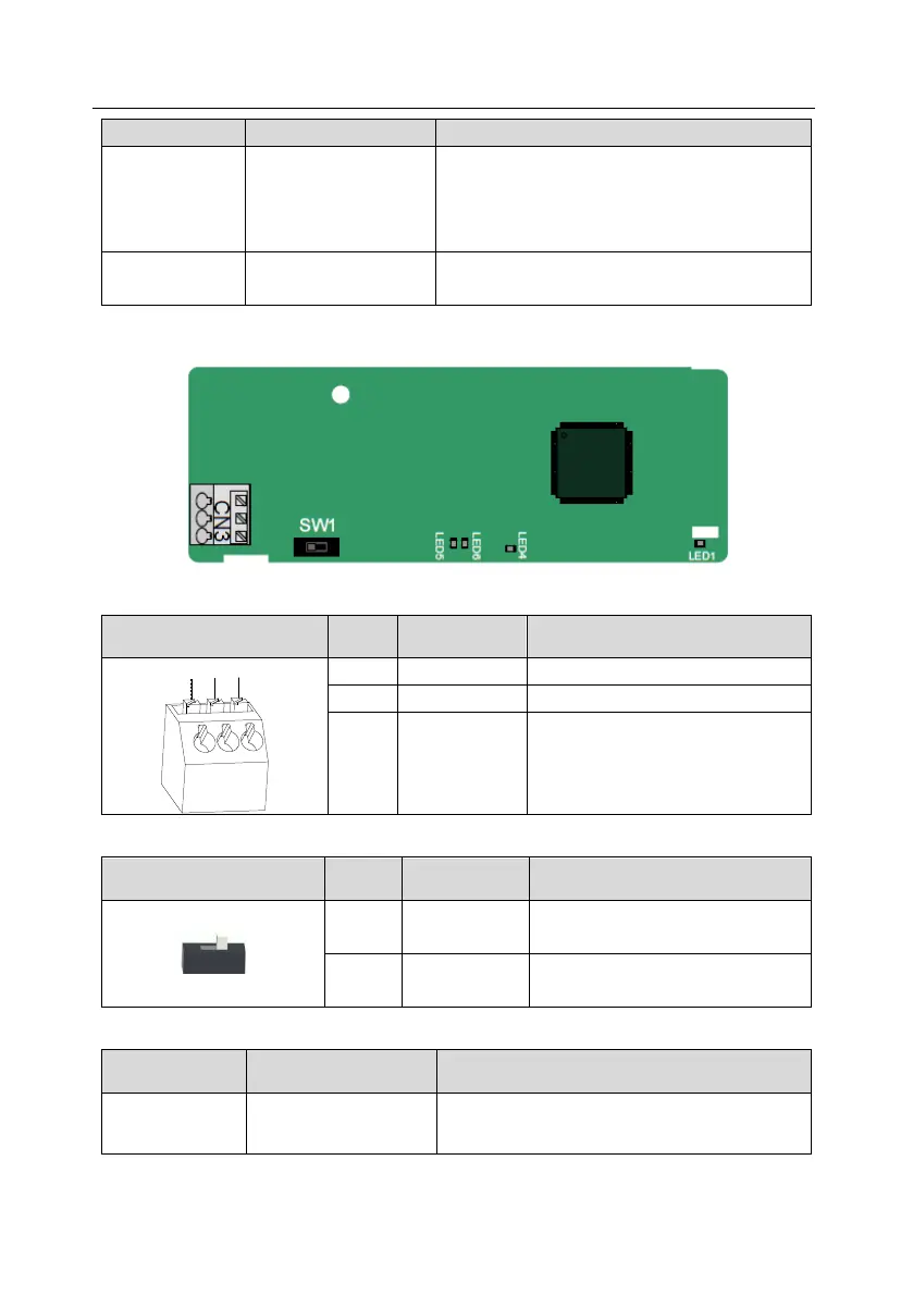
A.5.4 CANopen communication card (EC-TX505) and CAN master/slave control
communication card (EC-TX511)
EC-TX505/511 communication cards are user-friendly, adopting spring terminals.
CANopen bus high level signal
CANopen bus low level signal
The terminal resistor switch is described as follows:
CAN_H and CAN_L are not
connected to a terminal resistor.
CAN_H and CAN_L are connected to
a terminal resistor of 120 Ω.
The indicators are described as follows:
This indicator is on when the extension card is
establishing a connection with the control board;

 Loading...

