iMars grid-tied solar inverters Installation
32
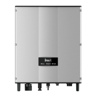
Figure 4.19 Pull out the rail
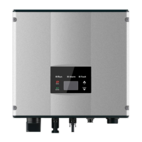
(5) Crimp the five wires(L1、L2、L3、N、PE) of the three-phase utility grid and the OT terminals firmly
to ensure that the conductor of the wire is not exposed, as shown in Figure 4.20;
Figure 4.20 Wire crimp terminal
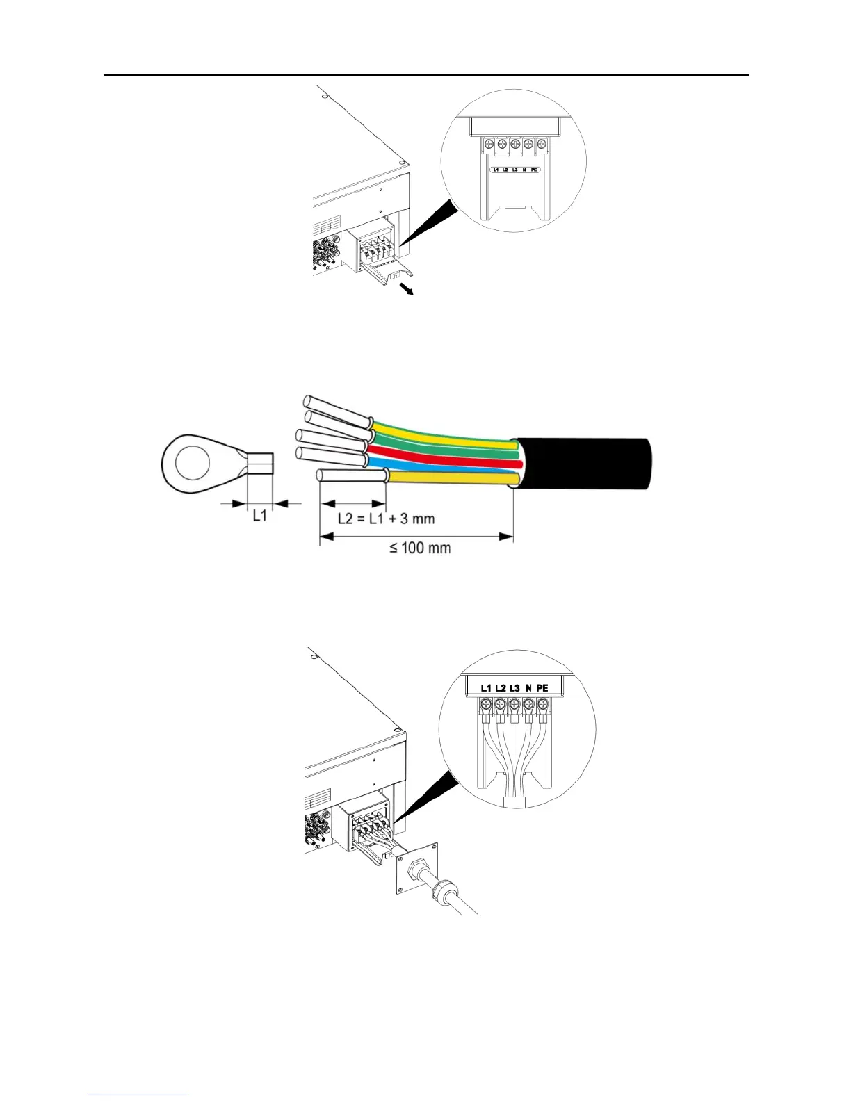
(6) The connection of AC cable and the connector should be correct and the screws are tightened.
The tightening torque is 2N•m, as shown in Figure 4.21.
Figure 4.21 Connection of wire and connector
(7) Push the AC terminal rail into the inside of the case and fix the rail with screws. Then lock the
waterproof cover of the junction box with the fixing screws. The tightening torque is 1.5 N•m.
Finally, tighten the waterproof connector to complete the waterproofing of the cable, as shown in
Figure 4.22.