48
LBK System Series| Instruction manual v1.2 SET 2021 |SAF-UM-LBKBus-en-v1.2|© 2020-2021 Inxpect SpA
4. Functioning principles
4.12.2 Network topology
The control units must be connected in a master/slave cabling topology. The following topologies are allowed:
Note: the maximum number of slaves that can be connected is 8.
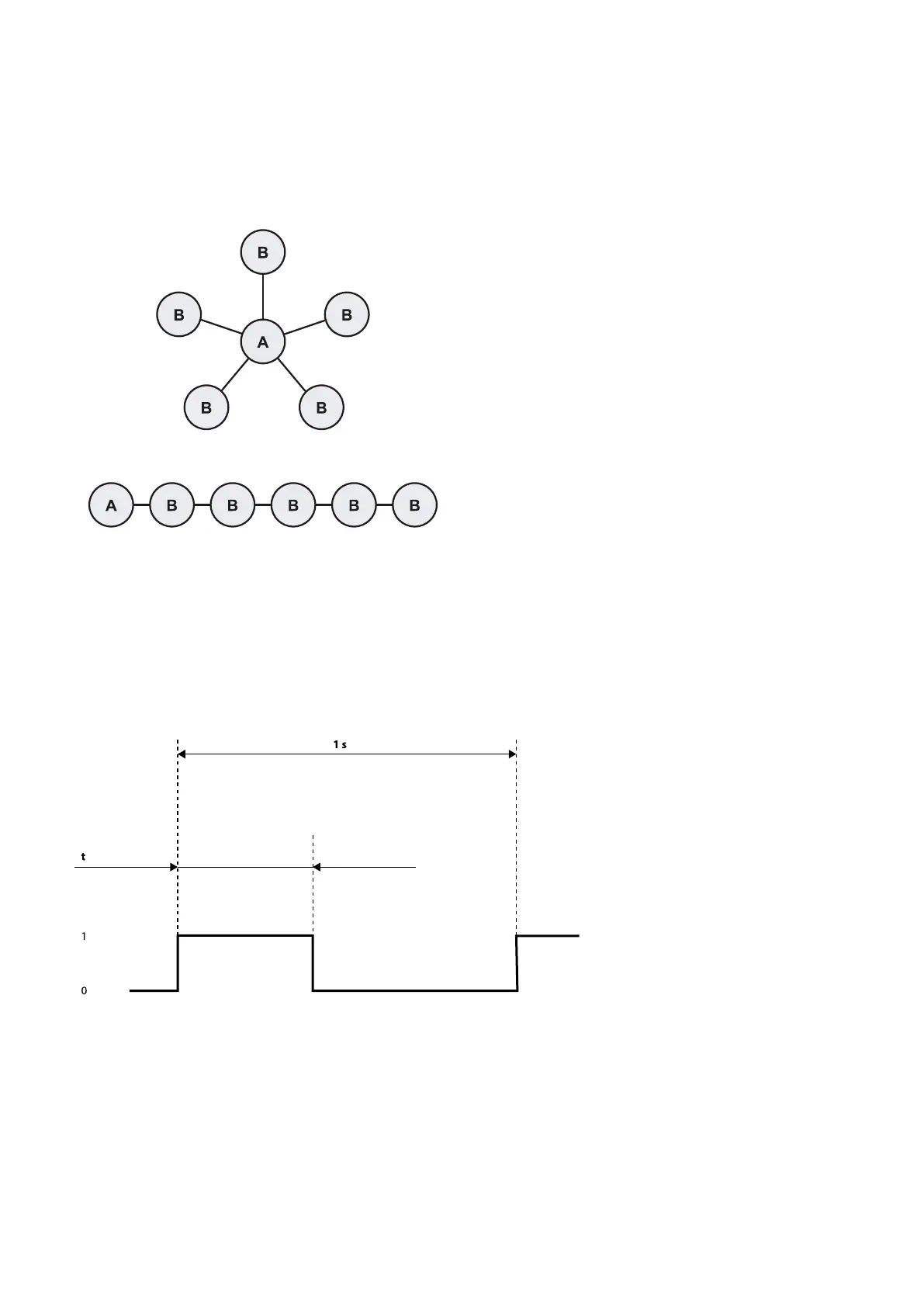
l Star: every peripheral node (slave B, i.e. control unit) is connected to a central node (master A, i.e. control
unit, PLC, or square wave generator).
Daisy chain (linear): this is accomplished by connecting each slave B (control unit) in series after the master A
( control unit, PLC, or square wave generator).
4.12.3 Trigger source
The following synchronization sources are allowed:
l Internal source: the source is the control unit, which acts as the network master.
l External source: the source is a PLC or a square wave generator, which acts as the network master.
4.12.4 Required signal
The control units need a 1 Hz synchronization signal frequency. The digital signal required from the trigger
(master) to all the control units (slaves) is described in the image below.
With t in the range [6 ms, 500 ms].
Synchronization takes place on the rising edge of the signal.
Note: if the trigger source is internal, the signal is automatically generated by the control unit (master).
Note: if the topology is daisy chain (linear), the signal is automatically propagated between the slaves without any
relevant delay.
4.12.5 Enable the multi-control unit synchronization function
1. For each control unit, in the Inxpect Safety application click Settings > Multi-control unit synchronization
and assign a different Control unit channel.