104
LBK System Series| Instruction manual v1.2 SET 2021 |SAF-UM-LBKBus-en-v1.2|© 2020-2021 Inxpect SpA
8. Technical references
8.5.3 Restart signal
Part Description
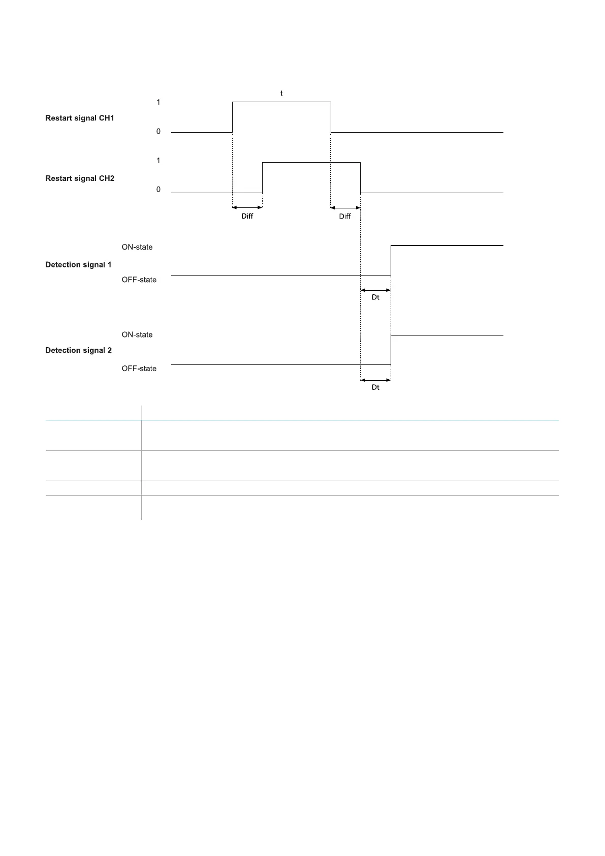
Detection signal 1
Detection signal 2
The Detection signal 1 and Detection signal 2 outputs go to ON-state as soon as the last
channel has correctly completed the transition 0 -> 1 -> 0.
Restart signal CH1
Restart signal CH2
Interchangeable channel. Both channels of Restart signal must have a transition of logical
level 0 -> 1 ->0. The time they stay at high logical level (t) must be at least 200 ms.
Dt Activation delay. Less than 50 ms.
Diff Less than 100 ms. If the value is greater than 100 ms, the system maintains the outputs
deactivated.