PART 4: INITIAL SET-UP
4.1 Battery/Power Supply Requirements
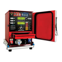
The Alpha MUTT
®
is a 12/24V DC device. Attempting to power the
MUTT
®
with anything other than a 12- or 24-volt DC power source
will destroy the internal circuitry and void the warranty.
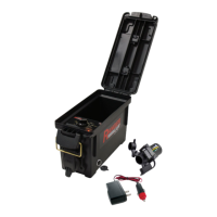
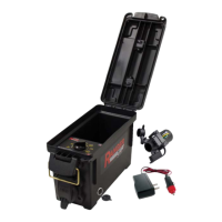
• The Alpha MUTT
®
Service-Truck Model requires an external
DC power source to function. A Group 31 or similar battery is
recommended.
• The Service-Truck Model does NOT have a built-in charger.
• The battery in the service truck must be maintained at a voltage between 12- and 14.5-volts DC.
Typically, batteries wired in parallel with the vehicle's own battery system will suffice.
• If running a dedicated power wire from a vehicle's main batteries, a 10-gauge wire is recommended
for runs up to 40’ and an 8-gauge wire is recommended for runs longer than 40’.
• All wiring must be able to carry a sustained current of 21 amps at 12V DC.
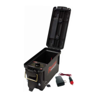
• An external (2 pin) DC power connector is provided with the tester. That power connector terminates
to a 2 prong SAE connector. A mating SAE connector on a 3’ cable with bare ends is also provided.
This cable can be used to make the connection to the vehicle's battery or dedicated wires.
• Follow standard battery wiring procedures. RED indicates Positive and Black indicates Negative.
When a cable has two black leads, if one lead has a white stripe, that lead is Positive.
• Prior to making connections, verify proper voltage orientation from the vehicle using standard
Automotive Style Volt Meters.
• The DC power connections require routine preventive maintenance to avoid downtime. The two-
prong connector should be disconnected and inspected once per month. Pins should be checked
for corrosion on both the cable and tester sides. If corrosion is present, clean connectors using
IPA
®
’s patented CLR156 Terminal Cleaners. Then clean the connections using IPA
®
8035A
DeoxIT
®
contact cleaner. Replace connector if needed. Check replacement parts section of this
manual for all related components.
4.2 Installing Shop Air
1. Be sure to leave an additional 18” of air-line length so the tester can
be pulled out via the slide-out base without damaging the air input.
A 3/8” OD coiled air hose extension is recommended.
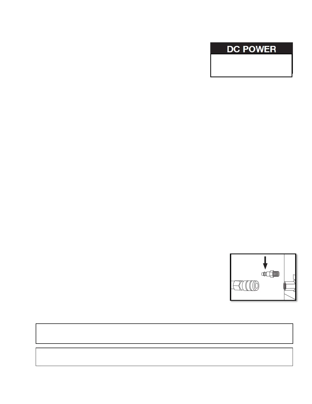
2. Locate the ¼” female NPT bulkhead fitting located near the
12V power input.
3. Install the male end of the air hose into the connector while firmly
holding a wrench onto the hex bulkhead to prevent any internal
components from becoming damaged.
WARNING: Listen for any air leaks where the shop air connects to the tester to avoid erroneous
results.
NOTE: It is always recommended to apply Teflon Tape to threads and then Pipe Dope over the
Teflon prior to assembling NPT fittings