ICP 3020 / ICP 4030 iMC-P Operating instruction
page 24
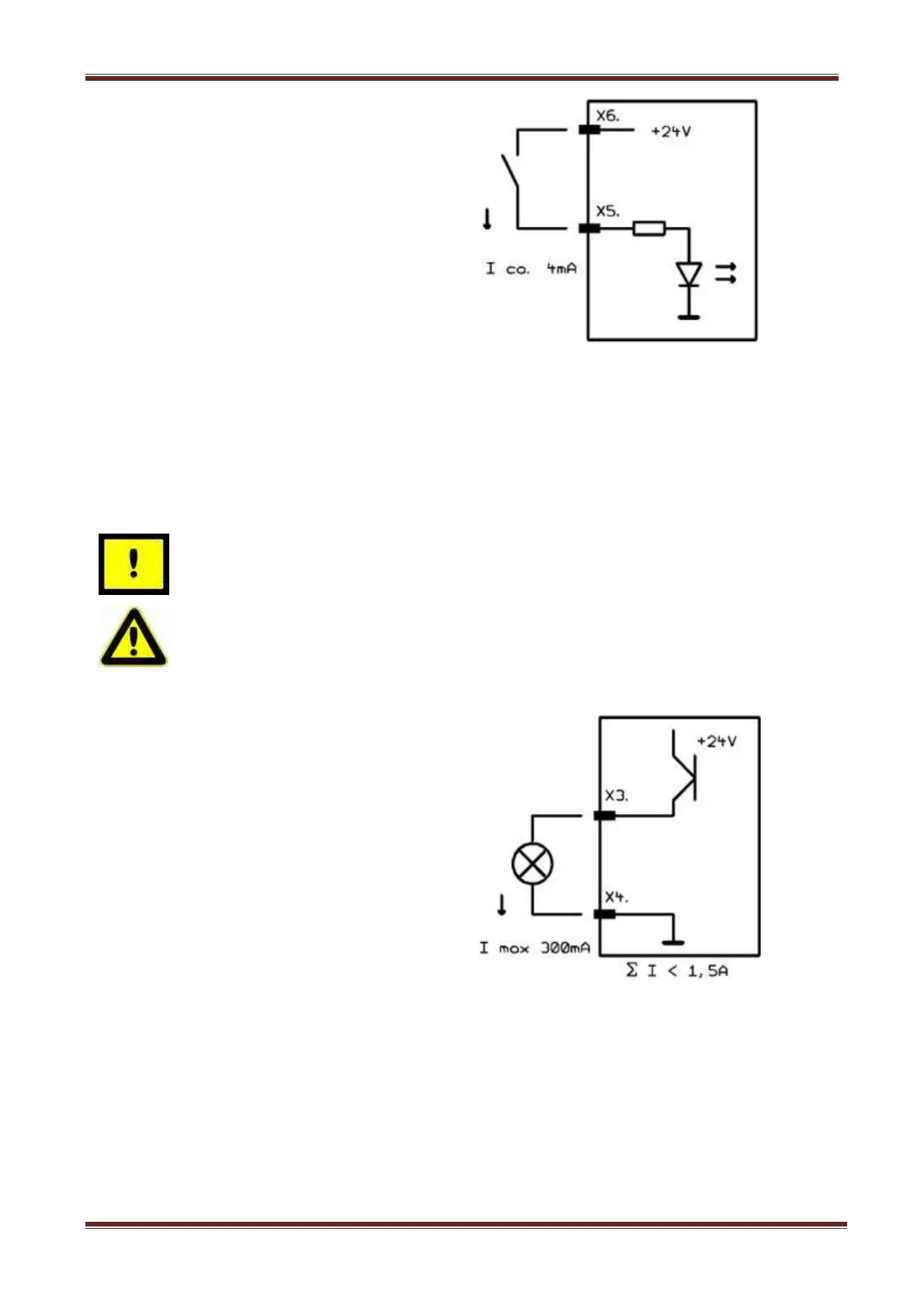
The binary user inputs 1 – 8 must be
wired as shown opposite.
The load of the controller internal 24V
power supply unit amounts on 1-active
state 4 mA per input.
Output - digital outputs, 8-pin connector
The controller has 8 digital user outputs. Use these outputs to connect external devices like
relays, or inputs from other devices. The maximum load of each relay output is 24 VDC/300
mA
Do not short 24VDC potential of the controller with GND or case
ground.
If you have pushed the emergency stop switch all states of the
binary user outputs will be maintained and not reset!
The binary user output 1 – output 8 must
be wired as shown opposite.
The transistor outputs (output 1 – 8) can
be rated with 300 mA per output.
If all outputs are switched (1-active) the
maximum load of the internal 24VDC
power supply unit is 1, 5 A (ca. 180mA
per output).