User manual
Strona 32 z 36 IU_M710P_MANUAL_05i00_ENG
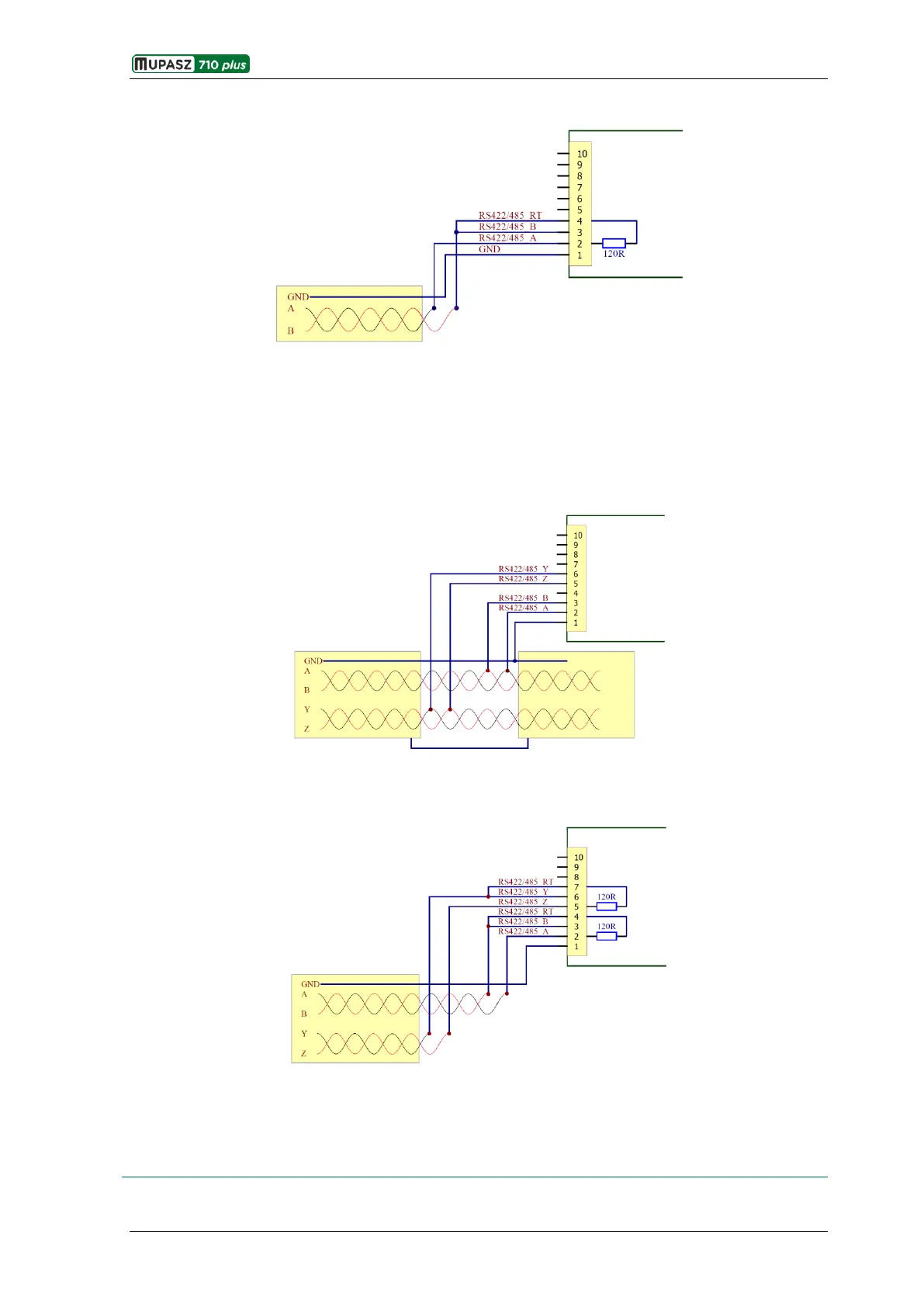
Type II (2-wire)
Fig. 4.1.2. Extreme position of the device in 2-wire communication network
It is also possible to connect devices to 4-wire RS-485 communication network. In this case pins 2, 3, 4 of
WAGO connector refer to direction of data transmission, pins 5, 6, 7 direction of data reception by the device.
Recommendations concerning wiring method for communication ports of devices installed at various
locations of communication network, are the same as for 2-wire version.
Type I (4-wire)
Fig. 4.1.3. Intermediate position of the device in 4-wire communication network
Type II (4-wire)
Fig. 4.1.4. Extreme position of the device in 4-wire communication network
It is recommended that shielded twisted pair is used, with characteristic impedance 120 and low wire-to-
wire capacity, with additional wire equalizing potentials of individual transmission modules. One end of
shielding wire should be connected with protective potential of the system.