This approximates the impeller position when it is set to 0.38 mm | 0.015 in. from the casing. Per-
form a final impeller adjustment after you install the impeller into the casing.
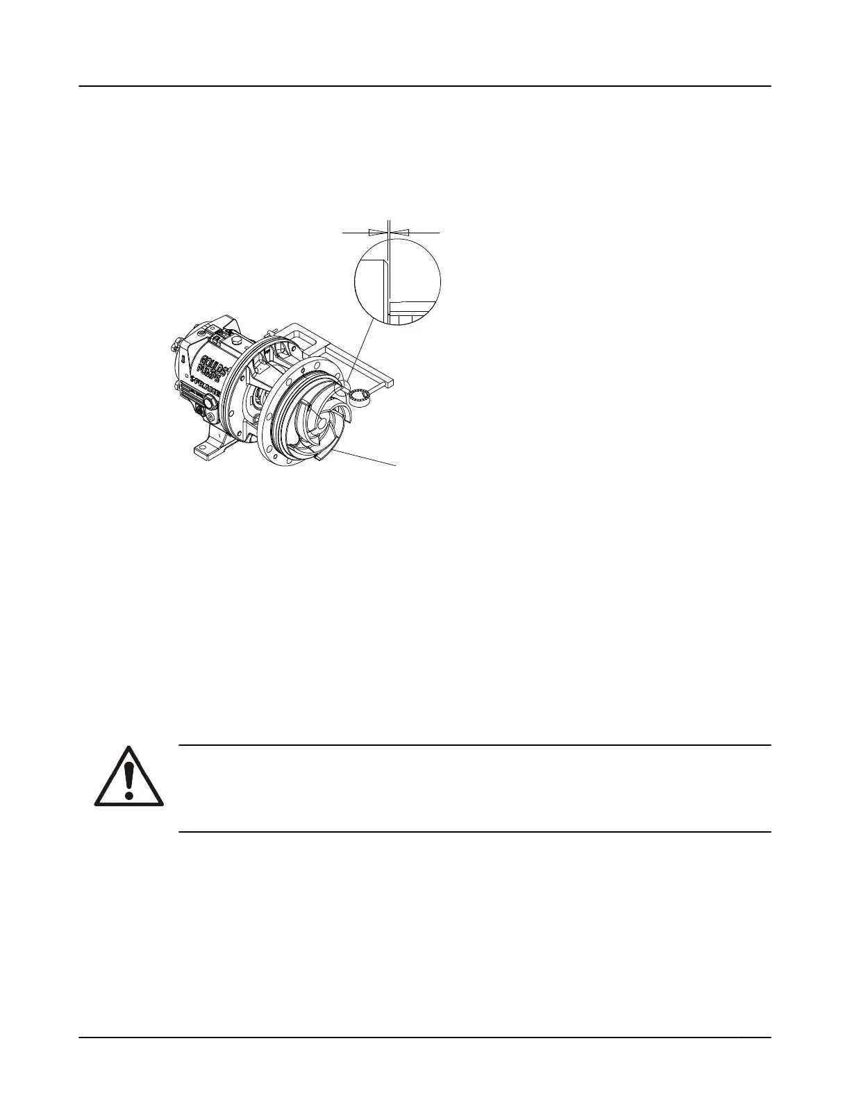
6. Check the impeller (101) runout.
Check vane tip to vane tip. If the total indicator reading is greater than 0.13 mm | 0.005 in., deter-
mine the cause and correct the issue before you proceed.
Figure 109: Check impeller run out
For more information on how to set the impeller clearances, refer to the Impeller-clearance checks and
Impeller-clearance setting sections in Commissioning, Startup, Operation, and Shutdown.
6.6.10 Post-assembly checks
Perform these checks after you assemble the pump, then continue with pump startup:
•
Rotate the shaft by hand in order to make sure that it rotates easily and smoothly and that there is
no rubbing.
• Open the isolation valves and check the pump for leaks.
6.6.11 Install the back pull-out assembly (except HT 3196)
WARNING:
Lifting and handling heavy equipment poses a crush hazard. Use caution during lifting and
handling and wear appropriate Personal Protective Equipment (PPE, such as steel-toed shoes,
gloves, etc.) at all times. Seek assistance if necessary
.
1. Clean the casing fit and install the casing gasket (351) on the seal chamber and stuffing-box cover.
2.
Loosen the clamping bolts (370C) and jack bolts (370D) on the bearing housing.
6.6 Reassembly
Model NM 3196 i-FRAME Installation, Operation, and Maintenance Manual 121
 Loading...