4. Repeat step 3 until the impeller becomes loose.
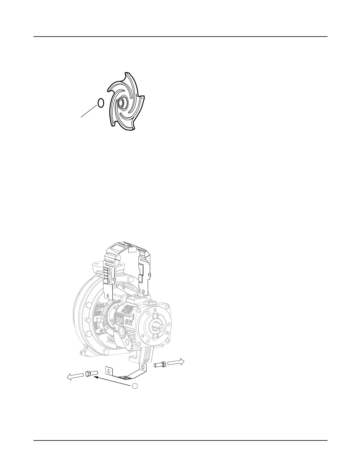
5. Remove and discard the impeller O-ring (412A).
You will insert a new O-ring during reassembly.
Figure 56: O-ring for models 3196, HT 3196, NM 3196, 3198, CV 3198 and 3796
If the impeller cannot be removed by the previous methods, cut the shaft between the gland and the
frame, remove the impeller, stuffing-box cover, gland, sleeve, and shaft end as a unit. Do not apply heat.
6.4.8 Shaft guard removal (if provided)
6.4.8.1 Remove the shaft guard (STi)
1. Remove the bolt for each shaft guard half that mounts the halves to each side of the frame.
2. Retain each guard half with fasteners for reinstallation.
Figure 57: Shaft guard removal
6.4 Disassembly
84 Model NM 3196 i-FRAME Installation, Operation, and Maintenance Manual
 Loading...