Electrical connections
6 720 802 419 (2012/06) en
32
10 Electrical connections
All regulation, control and safety devices on the heat pump are
connected and checked upon delivery.
B According to applicable regulations for connecting supply voltage.
Select cable area and cable type that corresponds to the relevant fuse
rating (Æ Chapter 7.3 ) and routing method.
B Connect the heat pump to the electric box connection strip according
to BS EN 60335 part 1 and via a switch with a minimum contact
distance of 3 mm (e.g. fuses, LS switch). Other consumers must not
be connected.
B Follow the relevant wiring diagram when connecting an earth breaker.
Only connect components that are approved for each market.
B Observe the colour coding when replacing circuit boards.
10.1 Connecting the heat pump
B Remove the front panel (Æ page 29).
B Remove the electric box cover.
B Route the connection cables to the electric box through the cable
gland in the roof plate of the heat pump.
B Connect the cables according to the wiring diagram.
B Reinstall the electric box cover and the front panel of the heat pump.
10.2 Soft starter
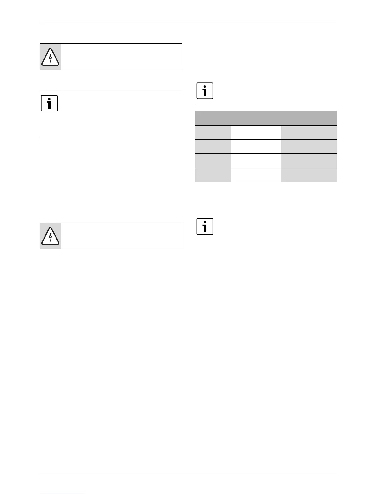
The soft starter has four different alarm causes, see table below.
Type 2 alarms are due to large voltage variations in the electricity grid.
Type 3 alarms indicate the existence of a fault in the compressor.
Types 4 and 5 alarms are there to protect the soft starter.
DANGER: Risk of electric shock!
B Switch off the main power supply before starting work
on the electrical part.
The heat pump's electrical connections must be able to
be disabled safely.
B Install separate safety switch that cuts all current to
the heat pump. A safety switch for each supply is
required for separate power supplies.
B Install a separate earth breaker for the heat pump.
CAUTION: Never grasp a circuit board without wearing a
ground-connected bracelet (Æ Chapter 3.10 ).
The soft starter has normally 1 minute restart delay. The
restart delay is 5 minutes at an alarm.
Number of
flashes red LED
Conditions Action
2Undervoltage (Ue
<190VAC
1)
)
1) <190 VACrms+/-2% at ≥ 1 s.
Auto reset with 5 min.
recovery
2)
2) Contact network supplier if alarm remains.
3Overcurrent during
start-up (>80A for 1 s.)
Auto reset with 5 min.
recovery
4Relay protectionUser action/possible
replacement of unit
5Incomplete rampAuto reset with 5 min.
recovery
Table 19
If same alarm is repeated even after manual restart, the
unit should be replaced (refers to 4 and 5 flashing
alarms).