Electrical connections
6 720 802 419 (2012/06) en
38
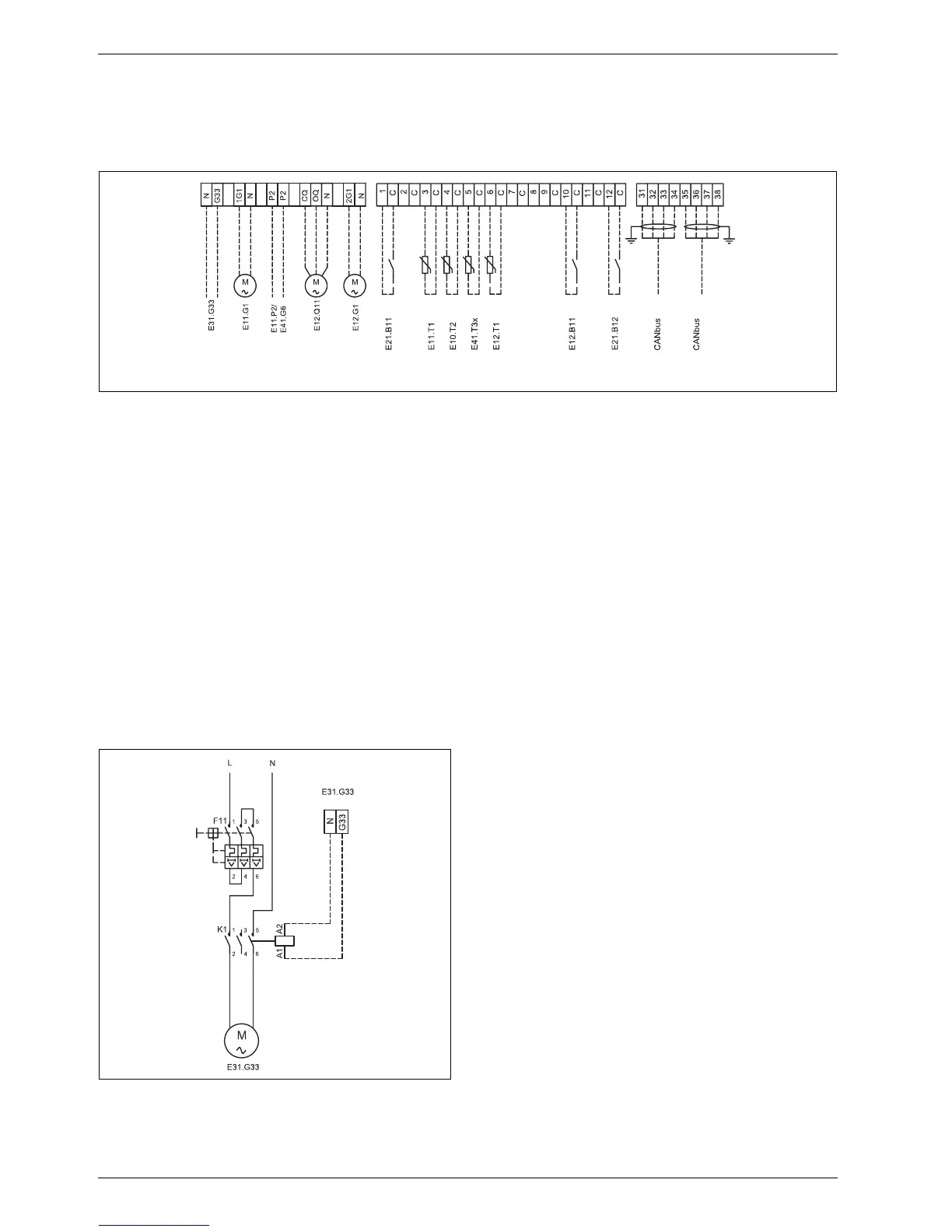
10.4 External connections
All external connections are made on terminal board PEL (low current)
and connection terminal blocks.
B High and low current cables should be routed separately in order to
avoid interference on the sensors (minimum distance of 100 mm).
B Use the following cable area when extending the temperature sensor
cable:
– Up to 20 m long cable: 0.75 till 1.50 mm
2
– Up to 30 m long cable: 1.0 till 1.50 mm
2
Fig. 35 External connections
Solid line = always connected
Dotted line = option, alternative:
[E31.G33] Control signal circulation pump ground water
[E11.G1] Circulation pump circuit 1
[E11.P2] General alarm
[E41.G6] Circulation pump hot water
[E12.Q11] Extra mixing valve circuit 2
[E12.G1] Circulation pump circuit 2
[B11] External input 1
[E11.T1] Flow circuit 1
[E10.T2] Outdoor sensor
[E41.T3x] Hot water
[E12.T1] Flow circuit 2
[E12.B11] External input, circuit 2
[B12] External input 2
10.5 Connection groundwater pump
Connect groundwater pump to the power supply with dedicated input
(230). The control to the contactor uses 230V which is taken from
terminals G33 and N in the heat pump.
Fig. 36 Connection groundwater pump
6 720 802 416-14.1I
6 720 802 416-15.1I