Function check
6 720 802 419 (2012/06) en
42
13 Function check
13.1 Refrigerant circuit
When the heat pump starts and there are quick changes in temperature,
bubbles may become visible in the sight glass Æ Figure 41.
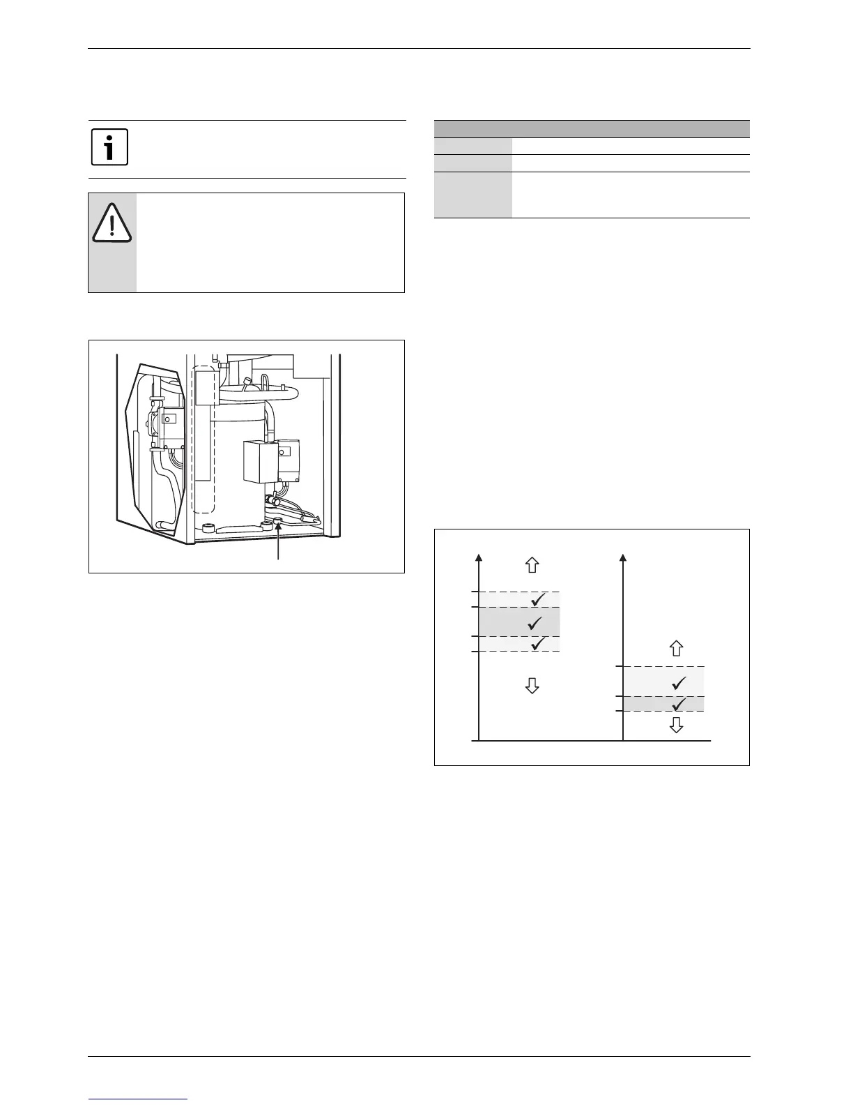
Fig. 41
In the event of constant formation of bubbles:
B Contact a service representative.
13.2 Filling pressure in collector circuit
The level in the vessel should not fall below the min-level 1/3. If the fluid
level is too low fill in as below:
The heat pump must be running all the time while filling.
B Remove the cover on the valve on top of the tank. Now carefully open
the valve.
B Check that the valve is fully open.
B Fill with anti-freeze (to 2/3) with the help of a clean watering can or
similar.
B Close the valve and finish by screwing on the cover.
13.3 Setting heating system operating pressure
B When the gauge is below 0.5 bar (in cold installation): Fill water until
the gauge shows approx 1 bar again.
B If there is a pressure drop: check the expansion vessel and heating
system for leaks.
13.4 Operating temperatures
Check the temperatures in the heat carrier and collector circuit after 10
minutes of operation:
• Temperature difference between heating system flow and return
approx. 7 ... 10 K.
• Temperature difference between collector circuit in and out approx. 2
... 5 K, recommendation: 2 ... 3 K.
When the temperature difference is too small:
B Reduce the speed of the corresponding circulation pump (G2 or G3)
in order to obtain a lower flow.
When the temperature difference is too great:
B Increase the speed of the corresponding circulation pump (G2) in
order to obtain a greater flow.
Fig. 42
[P2] Heat carrier pump G2
[P3] Collector circuit pump G3
[t
SA
]Temperature collector circuit out T11
[t
SE
]Temperature collector circuit in T10
[t
HV
]Temperature heat transfer fluid out T8
[t
HR
]Temperature heat transfer fluid in T9
The refrigerant circuit may only be opened by authorised
service engineers with refrigeration authorisation.
DANGER: Risk of toxic fumes!
The refrigerant circuit contains substances which, when
released or exposed to open fire, can form toxic fumes.
The fumes block the airways even at low concentrations.
B If the refrigerant circuit is not air-tight, the room must
be vacated immediately and properly aired.
6 720 641 855-09.1I
Pressure gauge reading
0.5 bar Minimum system pressure (when cold)
1 bar Normal filling pressure
1.5 bar Maximum system pressure at highest heating water
temperature:
must not be exceeded (safety valve opens).
Table 21
0 K
10 K
7 K
6 K
9 K
P2
P2
P2
t
HV
- t
HR
3 K
5 K
2 K
P3
P3
P3
P3 ( )
P2 ( )
P2 ( )
t
SE
- t
SA
6 720 612 299-04.3O