Settings
6 720 802 419 (2012/06) en
60
> Temperatures
All connected/acknowledged sensors present values. The set point
value is also given for some. The opportunity to correct the sensors is
also given.
Open circuits/short circuits/faults in sensors are indicated with a dash in
the display and under Temperatures. Alarms are triggered and
stored in alarm log and alarm history.
Deviation of T6 hot gas temperature
Details regarding the hot gas temperature at T6 are also displayed if the
actual value has deviated during the last 24 hours from the calculated
ideal value. This enables the status of the refrigerant circuit to be
assessed without special tools.
Deviations in excess of -10 °C can have the following causes:
• Filter E2x.V101 obstructed
1)
• Compressor run time too short
1)
• Incorrect temperature indication from an internal sensor
1)
• Expansion valve works incorrectly (too much open)
2)
Deviations in excess of +10 °C can have the following causes:
• Incorrect temperature indication from an internal sensor
1)
• The expansion valve does not function as it should (too closed)
2)
• Too little or too much refrigerant
2)
• Contaminants, magnetite and/or limescale deposits in the condenser
2)
1)
Inspection and remedy possible by the installer.
2)
Visit by an authorised refrigeration engineer with suitable tools for the
inspection and remedy is required.
> Programmable outputs
> Inputs
The status of all inputs is displayed here. Pressure switches and motor
cut-outs are shown for each heat pump. In addition, any alarms for
shunted additional heat, status for external inputs and protective anode
are shown.
Only connected inputs are displayed.
> Outputs
All components can be manually operated individually here to check
function.
>> Manual operation time
B Set the number of minutes for manual operation.
Different vital components can be put into operation/turned off
separately.
With 0min, status, e.g., On or Off, is displayed for each component.
Manual operation is possible for the following components (only the
ones that are installed are displayed):
>> G1 Heating circuit pump
>> Heat pump x
>>> Q21 Three-way valve (Heating/Hot water)
>>> G2 Heat carrier pump
>>> G2 Heat carrier pump speed
>>> G3 Collector circuit pump
>>> Compressor
>> Hot water electric heater
>> Hot water circulation pump
>> Circuit 2, 3...
>>> Circulation pump
>>> Mixing valve signal
>>> Mixing valve open
>>> Mixing valve close
>> Electric heater 1
>> Electric heater 2
>> Mixed additional heat
>>> Mixed additional heat
>>> Mixing valve signal
>>> Mixing valve open
>>> Mixing valve close
>> Alarm buzzer
>> General alarm
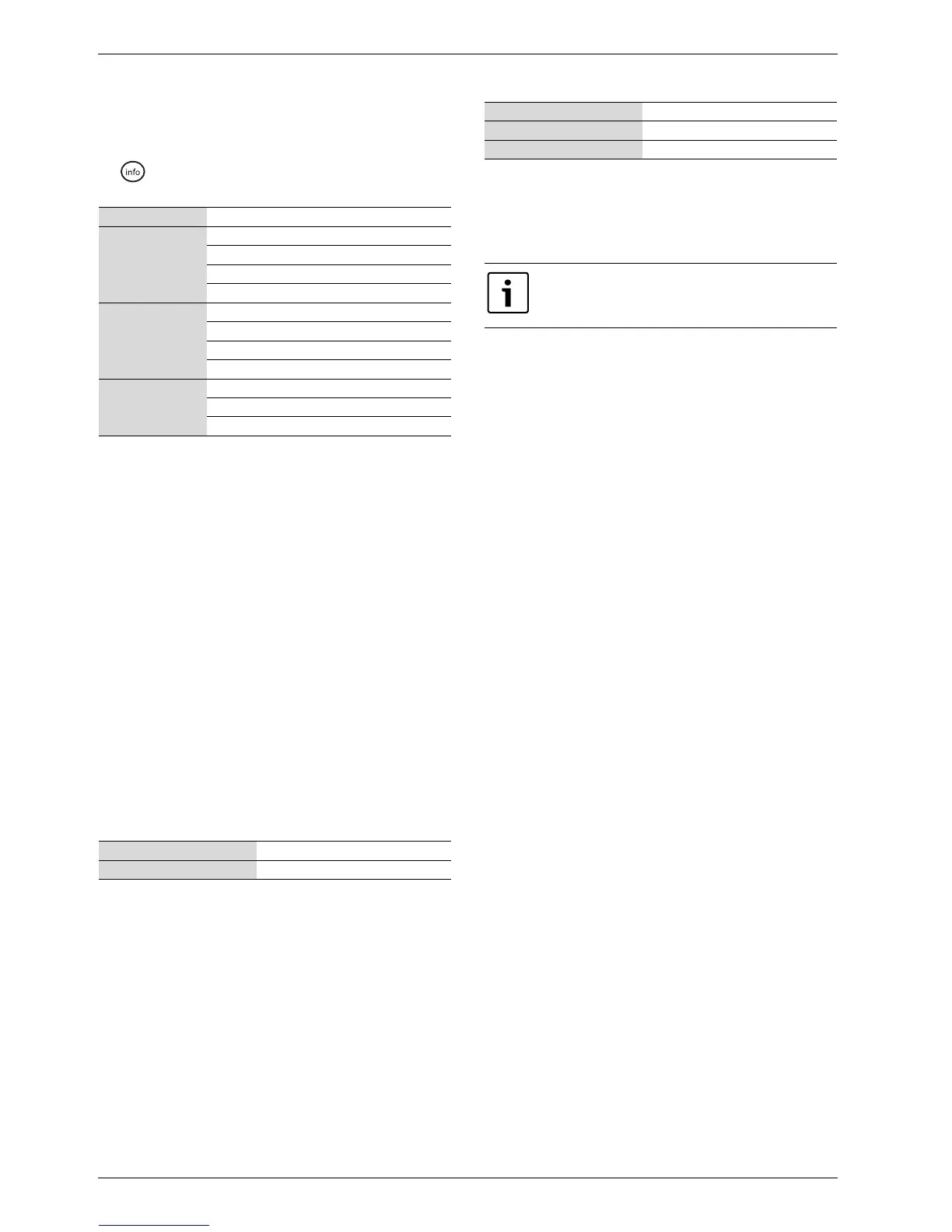
T2 Out T2 display, correction, Attenuation
Temperatures heat
pump x
T1 Start/stop limits compressor
T6,T8,T9,T10,T11 display, correction
T3 hot water start
T8 hot water stop
Circuit x T1 set point
T1 display, correction
T5 display, correction, Attenuation
Room temperature set point value
Hot water T3 display, correction
Extra hot water stop temperature
Hot water peak stop temperature
Table 125 Temperature display
Factory setting E11.P2
Alternative E41.G6/E11.P2
Table 126 Programmable outputs
Factory setting 0min
Lowest value 0min
Highest value 240min
Table 127 Manual operation time
Use the manual operation function on commissioning in
order to check if the installed components work.