Operation Manual – ITW GSE 7400 Battery Powered GPU
90 kVA
Transportation and Installation
Document No. 575.410DB Page 46 of 195
4.11 400 Hz Interlock
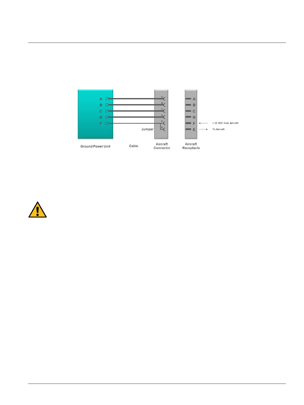
The interlock safety system ensures that the output contactor stays engaged for as long as the aircraft
connector is inserted into the aircraft receptacle. The aircraft provides 28 VDC on the F terminal with
respect to the 400 Hz neutral terminal.
Fig. 4.11.1 Standard Wiring Diagram for Civil Aircraft
For service, maintenance and testing purposes, the interlock system can be bypassed via the display
setup. To ensure personal health and safety, the ground power unit automatically returns to its initial
interlock mode once it receives 28 VDC at the F terminal, e.g. when the ground power unit is
connected to an aircraft.
To ensure personal health and safety, the interlock safety system must always be activated
unless the ground power unit is undergoing service, maintenance or testing by qualified
personnel.
4.12 400 Hz Input
The ITW GSE 7400 may be optionally equipped with a 400 Hz input, which is located on the left-hand
side of the ITW GSE 7400 (see picture on page 39), if the ITW GSE 7400 is expected to run out of
energy during a supply state. An additional 400 Hz Ground Power Unit can be attached to this inlet and
started. The ITW GSE 7400 will then automatically switch to the external 400 Hz by means of an NBPT
(No Break Power Transfer) and supply the aircraft attached to the output 1 with 400 Hz pass-through
power. As the ITW GSE 7400 switches the external GPU by using NBPT, no power interruption to the
attached aircraft will occur.
Note
This is only applicable for 400 Hz output no. 1.
All other outputs are terminated. If the unit has additional 400 Hz or 28 VDC outputs, they are turned
off and power to those outputs will be lost, as soon as the unit recognizes an external 400 Hz
connected to the 400 Hz inlet.


 To Next Page