19
INSTALLATION DIRECTIVE
N45 MNA M10
N67 MNA M15
MAY 2006
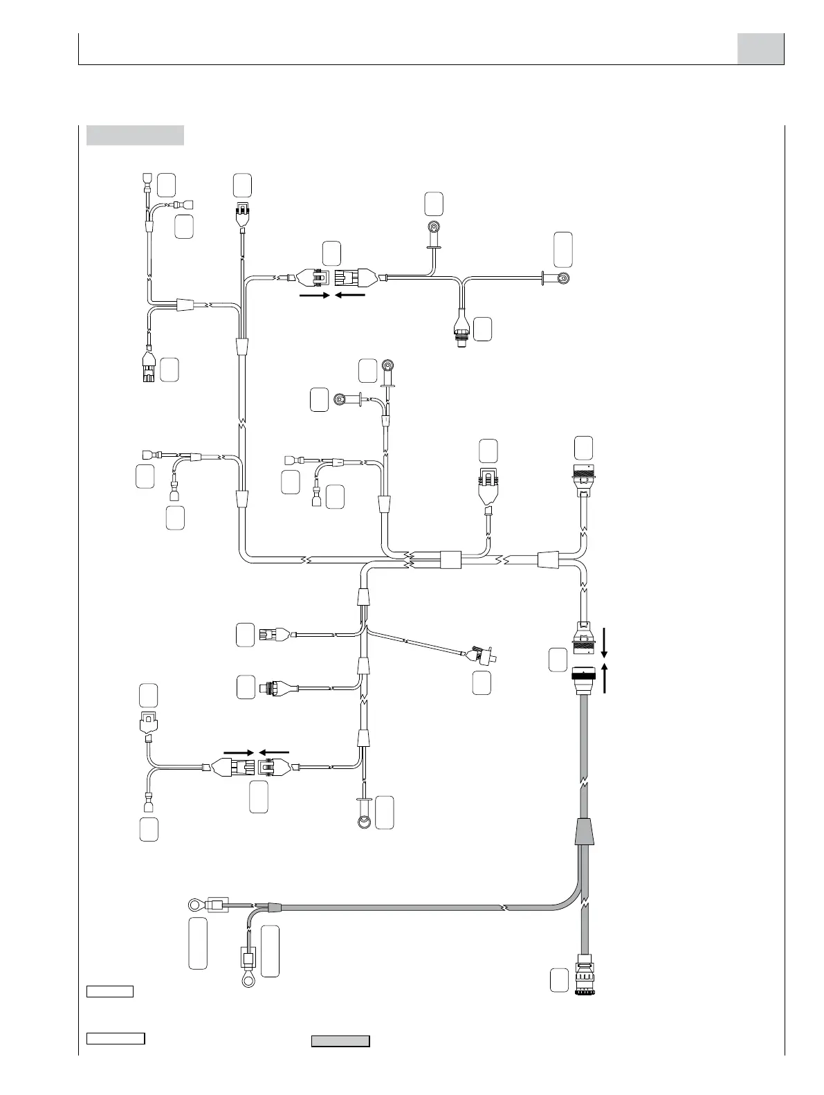
Wire harness
Figure 11
Engine wire harness Interface wire harness
04_409_N
JB
JA
– BATT
T
JF
GG
+ BATT
A
MM
I
B
T
O
W
W
V
V
K
K
C
EC
M
W
J1
J1
I1
KSB
A. Drive shaft sensor (on request) - B. Drive shaft sensor (on request) - C. Emergency shut-down push-button (on request, installer’s responsibility) - I. High coolant temperature
sensor (for alarm) - K. Air filter clogging sensor (for alarm) - M. Sensor for detecting the presence of water in the fuel pre-filter (for alarm) - O. Exhaust gas temperature sensor
(on request) - T. Coolant temperature sensor (for gauge) - V. Oil pressure sensor (for gauge) - W. Low oil pressure sensor (for alarm) - EC. Injection pump connector - I1. KSB
Refrigerating liquid temperature sensor - J1. Engine stop solenoid valve - KSB. Cold injection advance adjustment device - GG. Connector for alternator - J1. Alternator excitation
- W. Signal for revolution counter - JB. Instrument panel connection wire harness - JF. Relay box - MM. Electric starter motor.
 Loading...
