Figure 15
04_310_N
1
Relay box
1. JF Connection.
This shall be installed and anchored in such a way as
to dampen the vibrations and stresses occurring when
underway, and they shall be accessible during servicing
operations and when underway.
Inside the box, there are the relays to manage the power of
some parts and two fuses protecting the electrical lines from
accidental short circuits or power surge.
Connect it to wiring using the 16 poles JF connector.
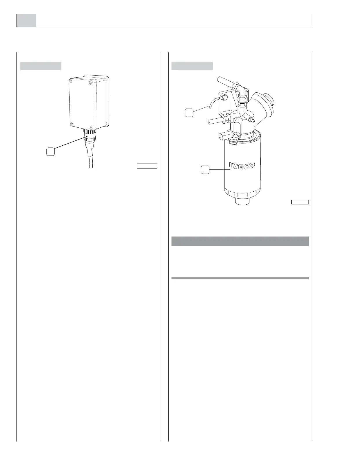
Water presence in the pre-filter sensor
1. Pre - filter - 2. Conductor to be connected
with the negative battery terminal.
CAUTION
In order to enable the proper working of the sensor to
detect water in the fuel, it is necessary that the pre-filter
support is connected electrically to the negative battery
terminal.
In the engine models which use parts with insulated poles
it is necessary to electrically insulate the pre-filter support
from the boat mass and then connect the support with the
negative battery terminal.
Figure 16
05_018_V
2
1
 Loading...
