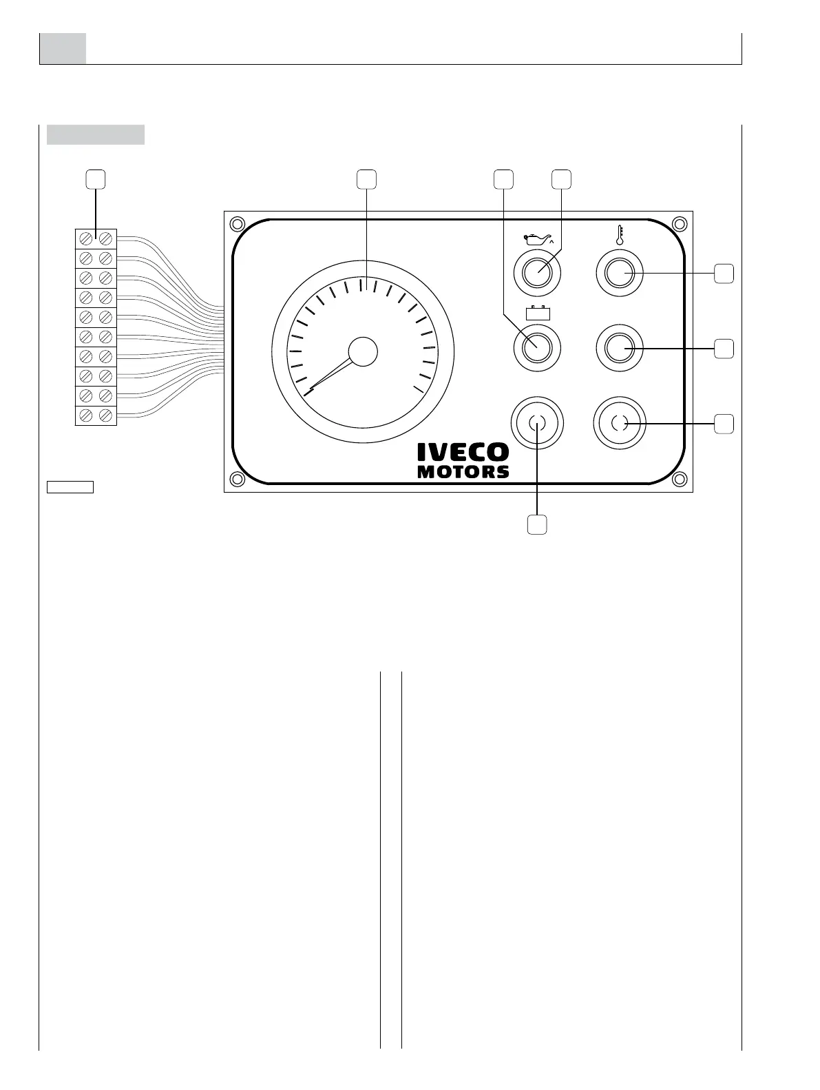
17. M10.01/M15.01 SECONDARY ANALOG INSTRUMENT PANEL (FLYING BRIDGE)
The secondary board MF clamp is connected to the main
board MP clamp. This connection requires a cable with 8
conductors to connect the wires with the same colour of
the two clamps. The warning light (6) is not used in this
model and consequently the two wires black and green and
black and red which are present in the MF clamp must not
be connected.
Installation
In order to drill holes on the area where the panel is to be
mounted, refer to the dimensions indicated in Chapter 18.
Operation of the secondary panel
After completing the electrical connection to the main panel
and engine preparation, and performing the tests required
for the first start (as described in Chapter 23), verify the
proper operation of the panel, proceeding as follows:
o Turn the key switch to the first position, thus enabling
the operation of both panels.
o Carry out the same tests for the secondary panel as
were carried out for the main panel.
o Disable the secondary panel by bringing the key switch
on the main panel to the resting or zero position.
Testing the engine start and stop function.
With the panel enabled, press the START push-button until
the engine starts, then release it; wait for engine rpm to sta-
bilize before stopping it by pressing the red push-button.
The starting and stopping operations can be performed sev-
eral times and consecutively from the secondary panel.
Checking indications
Proceed in the same way as for the main panel.
Figure 42
 Loading...
