13
INSTALLATION DIRECTIVE
N45 MNA M10
N67 MNA M15
MAY 2006
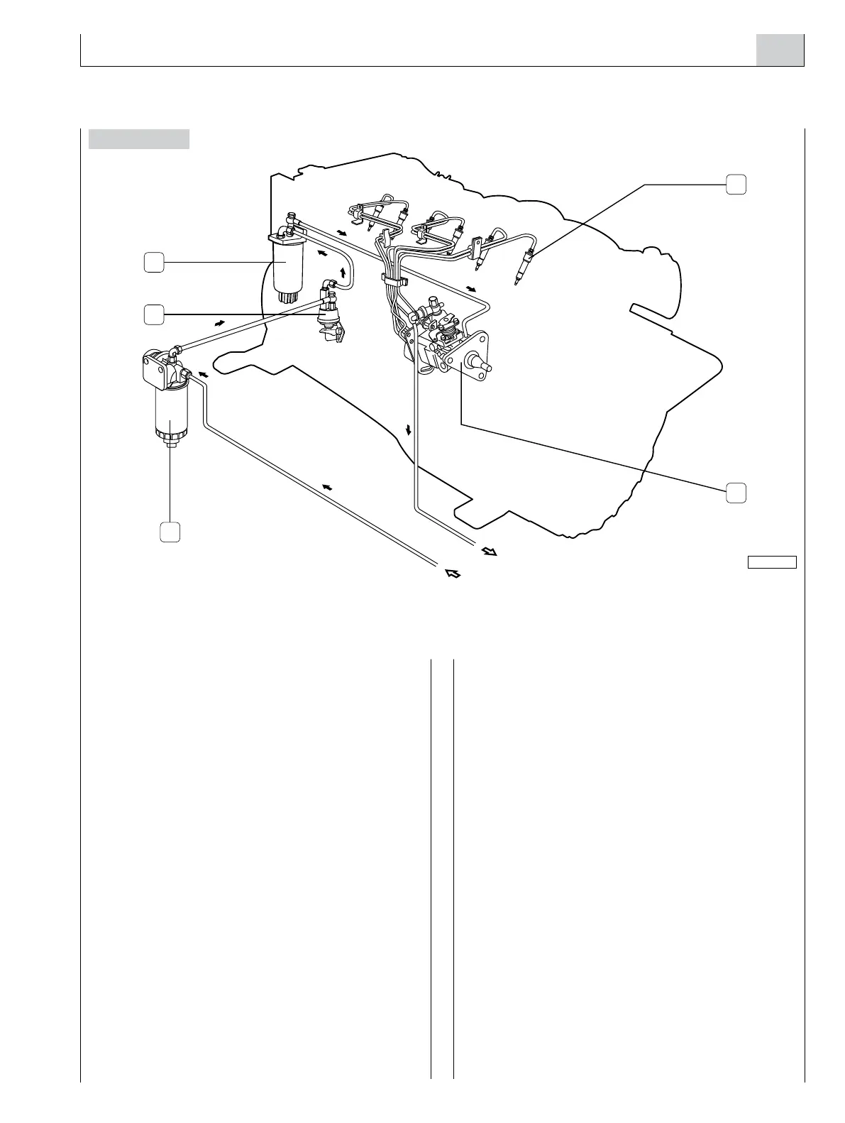
6. FUEL LINE
Figure 6
For the installation, the following connections are required:
- from the tank to the pre-filter
- from the pre-filter to feed pump intake
- from the fuel discharge outlet to the tank
Pre-filter
The pre-filter with priming pump, supplied separately from
the engine, must be fastened near the tank, in a relatively
low point of the line to allow for easy replacement of the
filtering cartridge and/or the operation of the hand pump.
Avoid the use of additional mesh or paper filters along the
feed lines between pre-filter and engine. To avoid introducing
impurities in the feeding lines inside the engine, do not place
filter cartridges pre-filled with fuel in the system.
Materials’ Characteristics
The fuel tank and the suction and return assembly must
withstand the continuous abrasion caused by a flow of fuel
oil of 150 l/h at a temperature of 100 °C without noticeable
deformation or wear or release of material. Use of metal
tanks, preferably made of iron alloys, is allowed, provided
they are connected to the negative terminal of the battery
to prevent the accumulation of electrostatic charges.
Tanks must be provided with vents to avoid exceeding
an internal pressure of ± 5kPa (± 0.5 m of H
2
O column);
their shape and the suction assembly must be such as to
assure a suction at the maximum longitudinal and transverse
inclination allowed for the boat, with a residual quantity of
fuel oil considered “reserve”.
The suction inlet should be positioned in such a way as to
avoid taking in sludge. The return flow must be in such a
way as to facilitate the mixing of the returning fuel with the
fuel in the tank. If the tank is lower than the filter, then the
return pipe must always be submerged. The pipes and union
fittings of the fuel line must withstand a fuel oil flow rate of
150 l/h at a temperature of 100 °C and a pressure of 3 bar
(300 kPa) without noticeable deformation, wear or release
of material. Metal tubes, preferably made of iron alloys,
are recommended, taking care to connect each individual
segment to engine ground to avoid the accumulation of
electrostatic charges and inserting a vibration damper
elastic joint on each segment. The pipes used must be
certified according to the relevant Countries’ rules or to the
standards issued by classification Bodies.
04_405_N
4
1
3
5
2
1. Settling prefilter - 2. Low pressure mechanical feed pump - 3. Fuel filter - 4. Injector - 5. Injection pump.
 Loading...