Figure 17
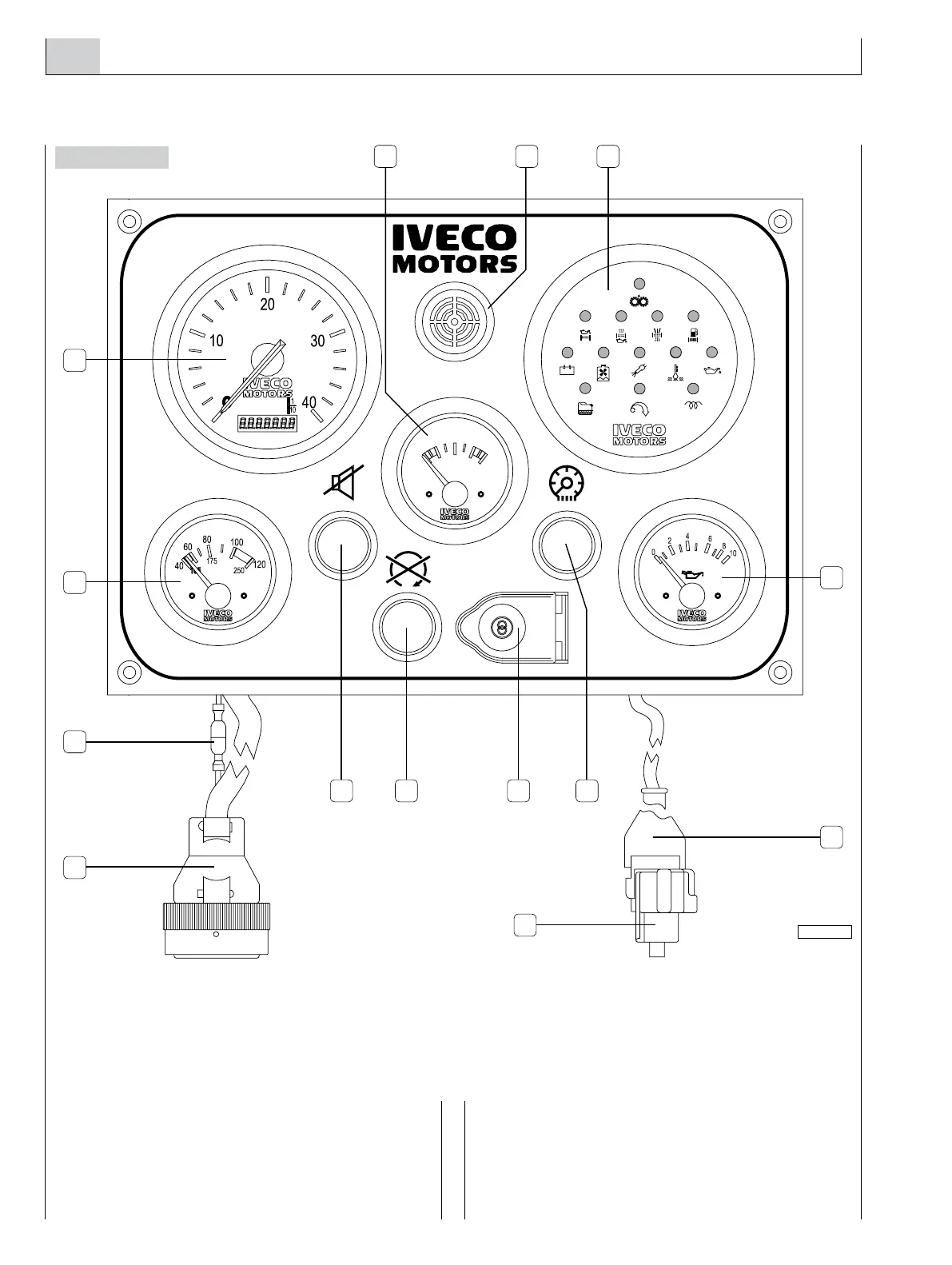
9. M10.00/M15.00 MAIN ANALOG INSTRUMENT PANEL
Installation of the IVECO MOTORS onboard panel with
analog indicators entails connecting the panel’s JC connec-
tor to the JB connector on engine wire harness, interposing
the appropriate extension wire harness available in 3, 5 and
7 meter-long versions. The JC-JB wire harness comprises 47
lines, each connected to the terminal identified on both con-
nectors by the same number.
To the main panel is connected the JE connector, provided
for connection to the secondary panel; in installations with
no secondary panel, do not remove the cap of the JE con-
nector to avoid compromising the electrical continuity of the
systems’ power supply circuit.
Do not disconnect the connector 14 to avoid wrong fuel
filter clogging alarm indication.
1. Coolant temperature gauge (TA) - 2. Revolution counter and hour counter (CG) - 3.Voltmeter (V) - 4. Buzzer (SA) -
5. Indications and alarms module (MS) - 6. Engine oil pressure gauge (MO) - 7. Connector for secondary instrument panel (JE) -
8. On board panel instrument light switch (L) - 9. Engine start/stop key switch (CA) - 10. Engine stop push-button (usable only on
versions with excitation engine stop) - 11. Sound alarm inhibition push-button (P1) - 12. Connector for main panel wiring (JC) -
13. Cap with electrical continuity connection - 14. SIFC Alarm abilitation connector.
 Loading...