25
INSTALLATION DIRECTIVE
N45 MNA M10
N67 MNA M15
MAY 2006
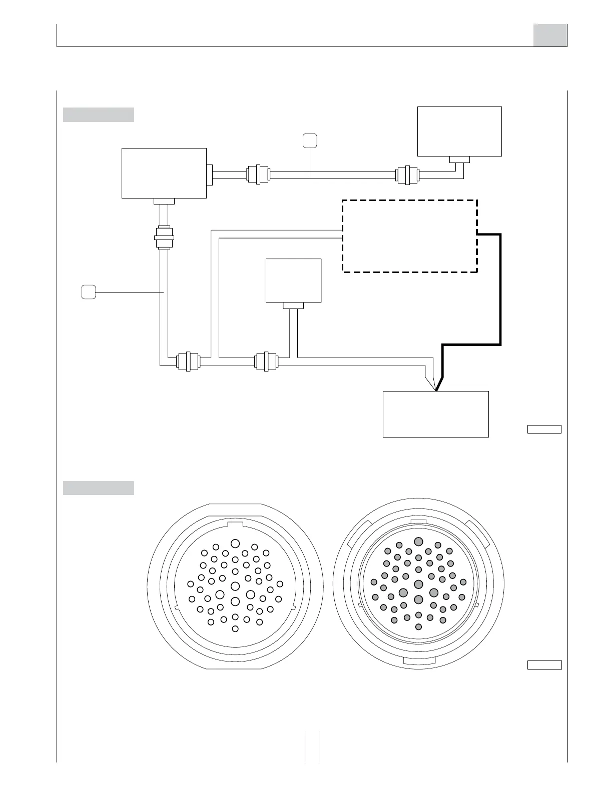
Synoptic of the connections of the analog panels
Figure 18
CONNECTORS OF THE JB - JC EXTENSION WIRE HARNESS, SEEN FROM THE COUPLING SIDE
Figure 19
To identify the functions served by the individual lines, refer
to the electrical diagrams in Chapter 13.
1. JB-JC xtension wire harness - 2. JE-JH extension wire harness.
04_254b_N
 Loading...
