53
INSTALLATION DIRECTIVE
N45 MNA M10
N67 MNA M15
MAY 2006
CAUTION
To assure the utmost reliability and safety while underway, all installations must be provided with the following alarm
indications:
(SATA) high coolant temperature
(SBPO) low oil pressure
It is also recommended that the following indications be present:
(SIFA) clogged air filter
(SS) alternator fault
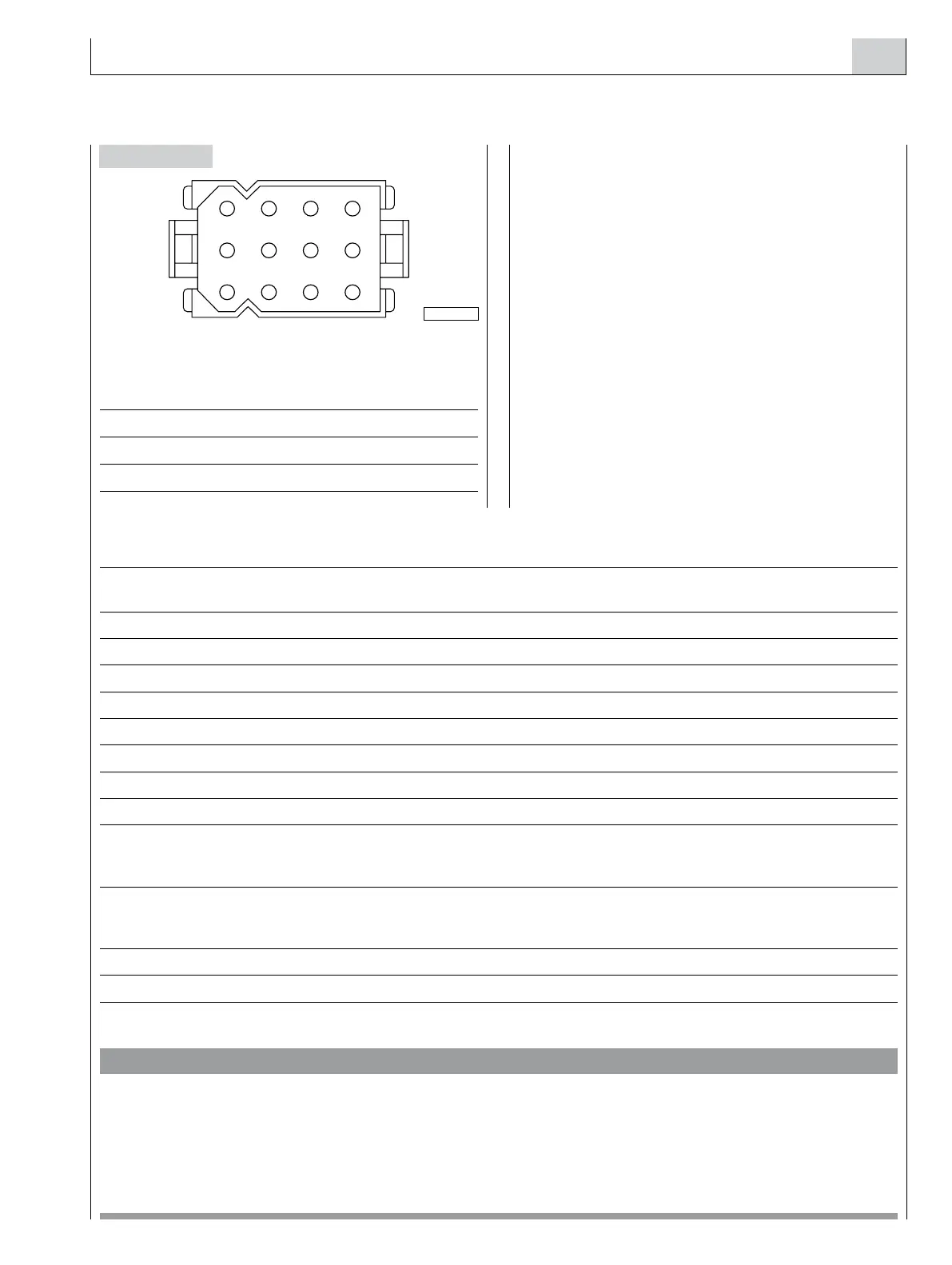
Functions of the JA terminals
PIN Description Electric level
OFF Indication ON Indication
1 Module power supply Positive (+B)
2 Module power supply Negative (ground)
3 High coolant temperature indication Open circuit Low (ground)
4 Overloaded or runaway engine indication Open circuit Low (ground)
5 Alternator fault indication High (+B) Low (1 to 3 V)
6 Low engine oil pressure indication Open circuit Low (ground)
7 Low engine coolant level indication Open circuit Low (ground)
8 Clogged air filter indication Open circuit Low (ground)
9 Engine stop command output Positive (+B) during the stop caused by the over speed
(for electro valves which stop
the engine when they are stressed)
10 Engine stop command output Circuit open during the stop caused by the over speed
(for electro valves which stop
the engine when they are not stressed)
11 Buzzer power supply High (+B) during the emission of sound
12 Buzzer power supply Negative (ground) during the emission of sound
VIEW FROM THE TERMINAL SIDE
OF THE COUPLING SIDE WIRING
connector IVECO code 8044005 ED
terminal IVECO code 8036141 ED
lid IVECO code 8044006 ED
JA connects the indications and alarms module to the electri-
cal system of the engine (sensors, power supply, etc.).
The terminal part of the wire harness, supplied with the
module, must be completed using female terminals, as
described in the electrical diagram of Chapter 20.
Gather essential information, the following ways must be
wired: 1, 2, 3, 5, 6, 8, 11, 12 with the female terminals sup-
plied as standard equipment, If the over-speed engine stop-
ping function is required, also the following circuits must be
wired: 4, 9, 10.
Figure 47
 Loading...
