20 J‐S180F/J‐S199F
InstallaonofTemperature
Controller
ControllerLocaon
MounngtheController
CableLengthsandSizes
• Thecontrollershouldbeoutofreachofsmall
children.
• Avoidlocaonswherethecontrollermaybecome
hot(neartheovenorradiantheater).
• Avoidlocaonsindirectsunlight.Thedigital
displaymaybedifficulttoreadindirectsunlight.
• Avoidlocaonswherethetemperaturecontroller
couldbesplashedwithliquids.
Indoormodelshavetheircontrollerbuiltintothe
frontpanel.Addionalcontrollerscanbeinstalled.
Thecableforthetemperat urecontrollershouldbea
non‐polarizedtwo‐corecablewithaminimumgauge
of22AWG.Themaximumca
blelengthfromeach
controllertothewaterheaterdependsonthetotal
numberofwiredcontrollersconnectedtothewater
heater.
NumberofWired
Controllers
MaximumCableLengthforeach
ControllertoWaterHeater
1 328(100m)
2 164(50m)
3or4 65(20m)
Turnthepoweroff.Donotaempttoconnectthe
temperaturecontrollerswiththepoweron.Although
thecontrollerisalowvoltagedevice,th ereis120volt
potenalnexttothetemperaturecontroller
conneconsinsidetheunit.
Donotconnectthetemperaturecontrollertothe
120VACterminalsprovide
dfortheoponalsolenoid
drainvalves.
WARNING
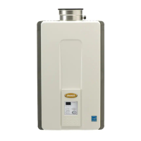
1. Makethreeholesinthewallasshown.
2. Runthecablebetweenthecontrollerandthe
waterheaterorthecontrollerandanother
controller.
3. Removethefaceplatefromthetemperature
controllerusingascrewdriver.
4. Connectthecabletothetemperaturecontroller.
5. Mountthecontrollertoth
ewallusingtheholes
drilledinstep1.
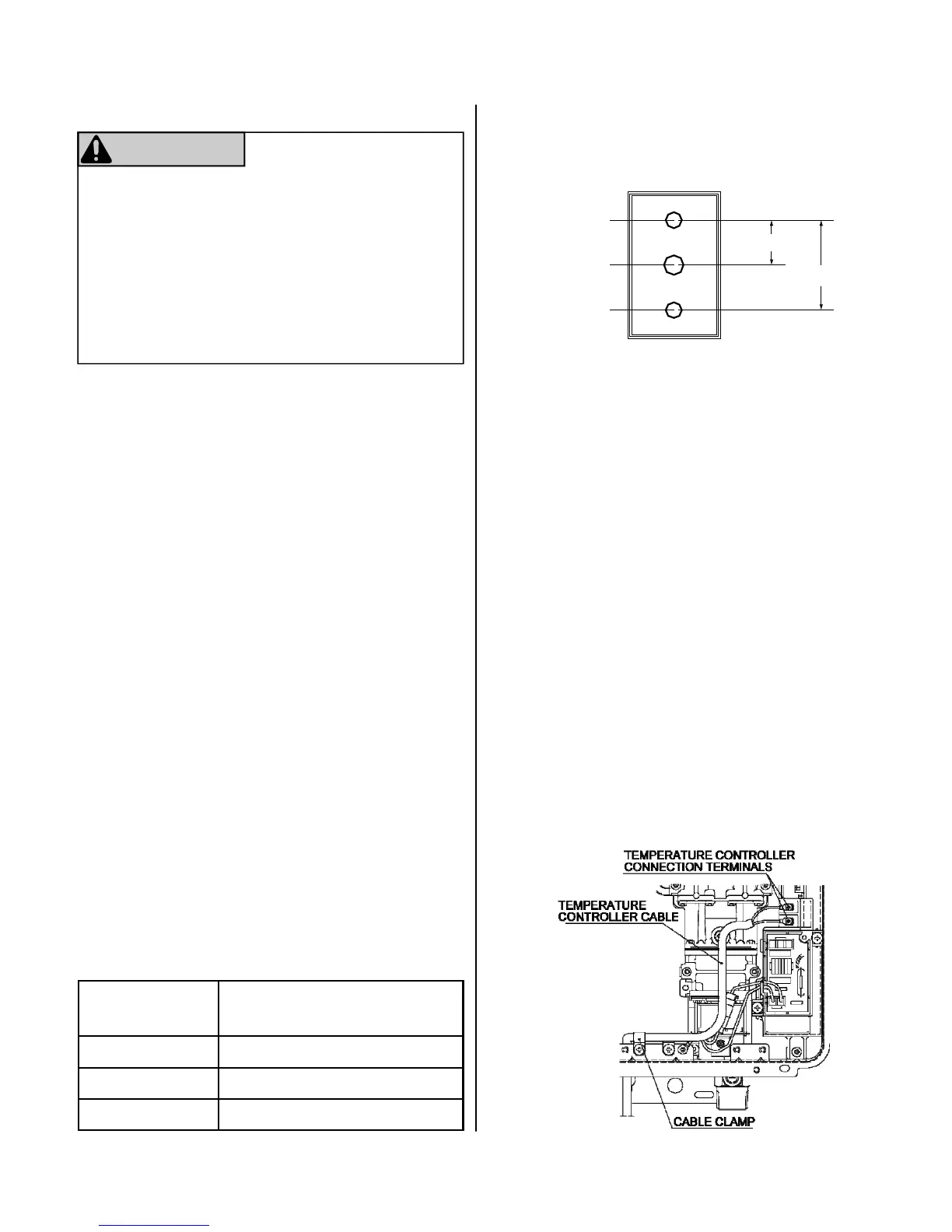
6. Disconnectthepowerfromthewaterheater.
7. RemovetheplasccoverfromthePCBand
electricalconnecons.
8. Threadthecablethroughtheaccessholeatthe
baseoftheunitandconnectthewirestothe
controllerter
minalsontherighthandsideboom
ofthePCB.
9. Securethecontrollercableusingtheclamp
provided.
10. ReplaceplasccoveroverPCBandthenreplace
thecoverofthewaterheater.
Outline of Remote
securing screw
1-21/32"
3-5/16
securing screw
wiring hole
 Loading...