J3020A Kit Installation Instructions
Page 14
1998-2006 Edition
This kit contains the f
ollowing parts:
One Air intake adapter housing w/ 4-3/4”(121mm) air Intake pipe
One 4-3/4” (121mm) End Cap/ Rodent Screen
One 19” (483mm) length of 3” (76mm) exhaust pipe w/belled end
One Wall Thimble (2 pieces)
One 3” (76mm) Double Wall Rain Cap w/ Rodent Screen
Sixteen 1/2” #8 Hex Head self drilling & tapping Screws (Teck Screw)
T
ools and other materials required:
Hand Drill with 1/4” Hex Driver
Appropriate Saw(s) to Cut 9” (229mm) Diameter Hole in Wall
Phillips Head Screw Driver
Power Drill, Phillips bit
Caulking gun with a tube of High Temperature RTV silicone
Wall Material
Wood
Sheet Metal
Masonry
Dry Wall
Recommended Screw Type
3/4” #6 Wood Screw
1/2” #6 Sheet Metal Screw
1-1/2” Molly Bolts
1” #6 sheet metal screws with plastic anchors
This kit contains all the materials, except 8 screws, that are needed to secure the wall thimble to the wall.
The type of screws needed depends on the type of wall material. The recommended type of screw for each
type of wall material is listed below:
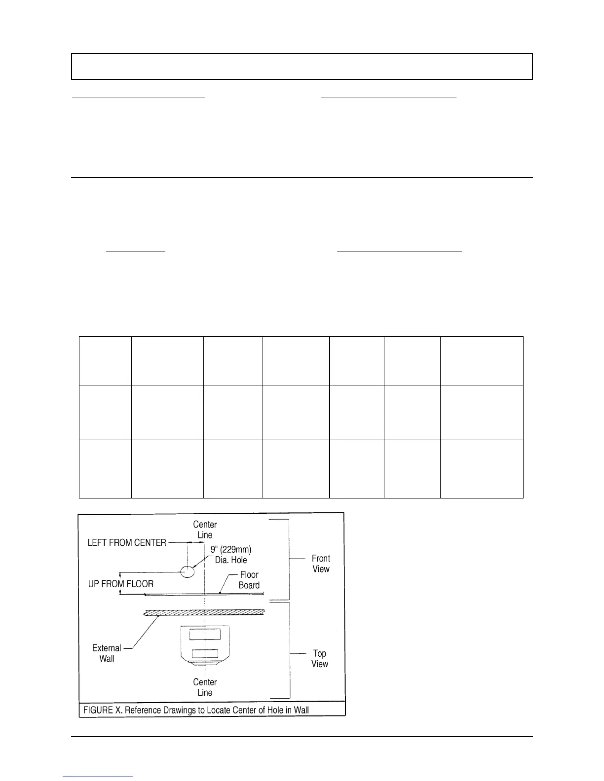
LEFT: Left of the center line as shown in Figure X.
UP: Up from the top of the floor board as shown in
Figure X.
1. Determine the final position for the stove and
refer to Chapters III and IV (Clearances to
Combustible Materials Requirements) to ensure
that the final position of the stove adheres to all
the listed requirements.
2. Determine the center of the 9" (229mm) hole
that needs to be cut in the wall by using Figures
X and the table above. Example: J1000 w/ Legs.
find the center line as in Figure 2. Move 1/8"
(3mm) to the left of the center line and up 8-3/4"
(222mm) from the floor. This point is the center of
the 9" (229mm) diameter hole.