Page 6
ENGLISH
Jandy
®
Pro Series, CS Single Element Cartridge Pool & Spa Filter
|
Installation & Operation Manual
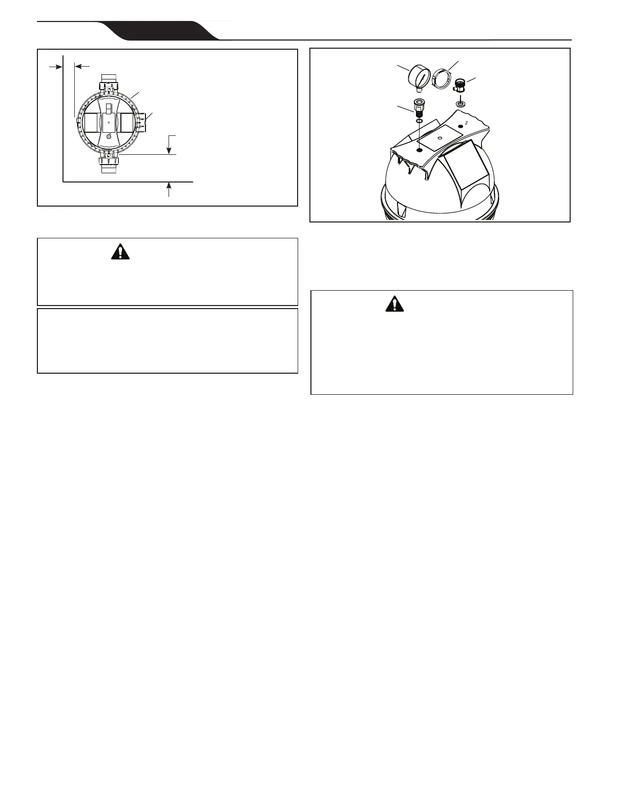
Figure 2. Pressure Gauge and Pressure Release
Assembly
Air Release Valve
Pressure Gauge
Pressure Gauge
Adapter
Clean/Dirty Snap Ring
WARNING
Water discharged from an improperly positioned filter
or valve can create an electrical hazard which can
cause death, serious injury or property damage.
CAUTION
Maintain your pressure gauge in good working order.
The pressure gauge is the primary indicator of how the
filter is operating.
5. Allow sufcient space above the lter to remove
the lter lid and lter element for cleaning and
servicing.
6. Position the lter to safely direct water drainage.
Align the air release valve to safely direct purged
air or water.
7. If the lter is to be installed below the water level
of the pool, isolation valves should be installed on
both the suction and return lines to prevent back
ow of pool water during any routine servicing
that may be required.
3.2 Filter Preparation
1. Check carton for damage due to rough handling
in shipment. If carton or any lter components are
damaged, notify carrier immediately.
2. Carefully remove the accessory package. Remove
the lter tank from the carton.
3. A visual inspection of all parts should be made
now. See parts list in Section 9.
4. Install the pressure gauge and adapter assembly to
the threaded hole marked "Pressure Gauge" at the
top of the lter See Fig. 2.
5. Install the air release valve into the threaded
opening marked "Air Release" at the top of the
lter. See Fig. 2.
NOTE Teflon tape is included in the accessory bag.
3.3 Filter Installation
WARNING
To avoid an electrical shock hazard, which can result
in serious injury or death, ensure that all electrical
power to the system is turned off before approaching,
inspecting or troubleshooting any leaking valves or
plumbing that may have caused other electrical devices
in the surrounding area to get wet.
1. This lter operates under pressure. When the
locking ring is properly seated and the lter is
operated without air in the water system, this lter
will operate in a safe manner.
2. If the system can be subjected to higher pressures
than the maximum working pressure of the lowest
rated component, install an ASME
®
approved
automatic Pressure Relief Valve or Pressure
Regulator in the circulation system.
3. Place the lter on the concrete pad, lined up with
the inlet and outlet pipes.
4. To reduce pressure losses, 2" (minimum) piping
is recommended for plumbing the system.
Never exceed the manufacturer's maximum
recommended lter ow rates.
5. For best efciency use the fewest possible
number of ttings. This will prevent a restriction
of the water ow.
6. Make all plumbing connections in accordance
with local plumbing and building codes. Filter
unions are provided with an o-ring seal. Use
silicone based lubricants on the o-rings to avoid
damage. Do not use pipe joint compound, glue
or solvent on union threads.
7. Keep piping tight and free of leaks. Pump suction
line leaks may cause air to be entrapped in lter
tank or loss of prime at the pump. Pump discharge
line leaks may show up as equipment pad leaks or
air being discharged through the return lines.
Figure 1. Filter Location - Top View
Filter
12" Minimum
Clearance
6" Minimum Clearance
Drain