Page 10
heater about 15 minutes before the filter pump shuts
off. To install a time clock auxiliary switch into the
heater wiring, follow these steps (see Figure 11):
1. Remove the service door.
2. Remove the factory-installed wire between
terminals 1 and 2 on the terminal block
(see Figure 5).
3. Connect the wires from the time clock
auxiliary switch to the two terminals. Use 14
gauge copper wire with insulation at least 1.2
mm thick, and a temperature rating of 105
degrees Celsius (°C) or greater. The length of
the wire between the heater and the time
clock should not exceed 4.57 m. The contact
points of the time clock switch should be
silver, or a low resistance alloy.
2I. Water Piping
2I-1. General Information
High temperature plastic piping (CPVC Sched-
ule 80) may be connected directly to the inlet/outlet
header providing that the controls keep the filter pump
running at least 15 minutes after the heater is turned
off. Plastic materials may be used in pipes, fittings,
grids, and other elements of the filter system if accept-
able by the authorities having jurisdiction (see Figure
12). If unacceptable, use a metal heat sink pipe
between the filter and the heater (see Figure 15).
Install a check valve if there is any chance of
back siphoning when the pump stops (see Figure 13).
Do not install any other valve or variable restriction in
the piping between the heater outlet and the pool,
unless it is necessary to increase back pressure, or is
being used as a diverter valve.
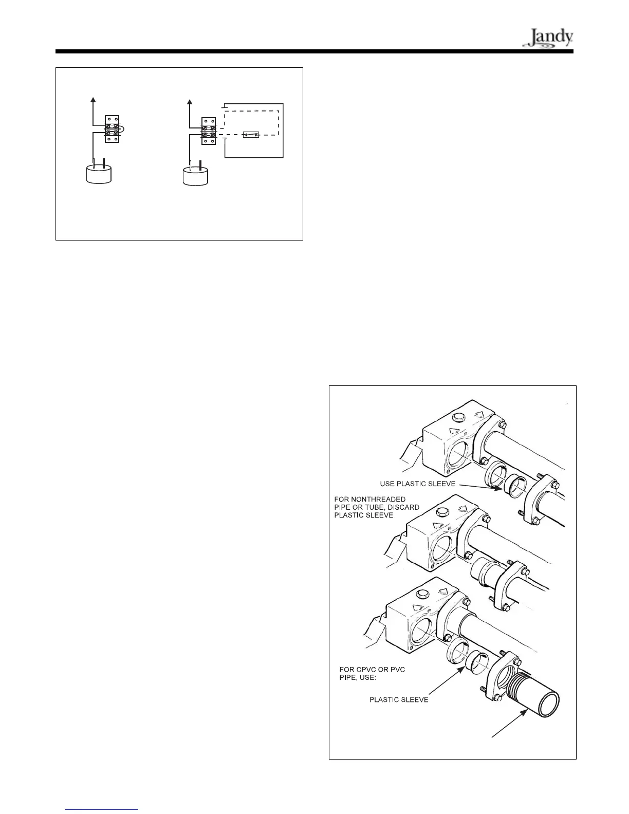
The heater has 50 mm universal header cou-
plings. You can connect threaded 50 mm iron or
copper pipe or unthreaded 38 mm iron or copper pipe
without an adapter. CPVC pipe can be used by first
installing the CPVC nipples, provided with this heater,
into the cast iron fittings (see Figure 12).
2I-2. Automatic Chlorinators (Chemical
Feeders)
Any excessive concentration of chlorine in the
pool heater can be very destructive. Heater damage
caused by an excessive concentration of chlorine is not
covered by the warranty. All chlorinators should be
downstream of the heater.
Equip the chlorinator with an anti-siphoning
(back flow) device so that chlorine will not siphon
into the heater after the pump is shut off.
Wire the chlorinator so it cannot operate unless
the filter pump is running. If the chlorinator has an
independent clock control, be sure the filter and
chlorinator clocks are synchronized.
Figure 11. Time clock wiring.
Figure 12. Piping connections.
TO LIMIT SWITCHES TO LIMIT SWITCHES
FIELD PROVIDED WIRING
LOW VOLTAGE
SWITCH
TIME CLOCK
FUSIBLE LINK FUSIBLE LINK
WHITE
WHITE
FACTORY
INSTALLED
WIRE
WHITE
WHITE
HEATER WIRING
BEFORE MODIFICATION
MODIFIED HEATER
WIRING WITH TIME
CLOCK INSTALLATION
METHOD FOR INSTALLING
50 MM THREADED PIPE
CPVC
NIPPLE PROVIDED
 Loading...


