Page 11LITE 2 MODEL LG POOL AND SPA HEATER
If the chlorinator is equipped with its own pump,
install it so that it introduces the chlorine downstream
from the heater, and, if possible, below the level of the
heater outlet fitting.
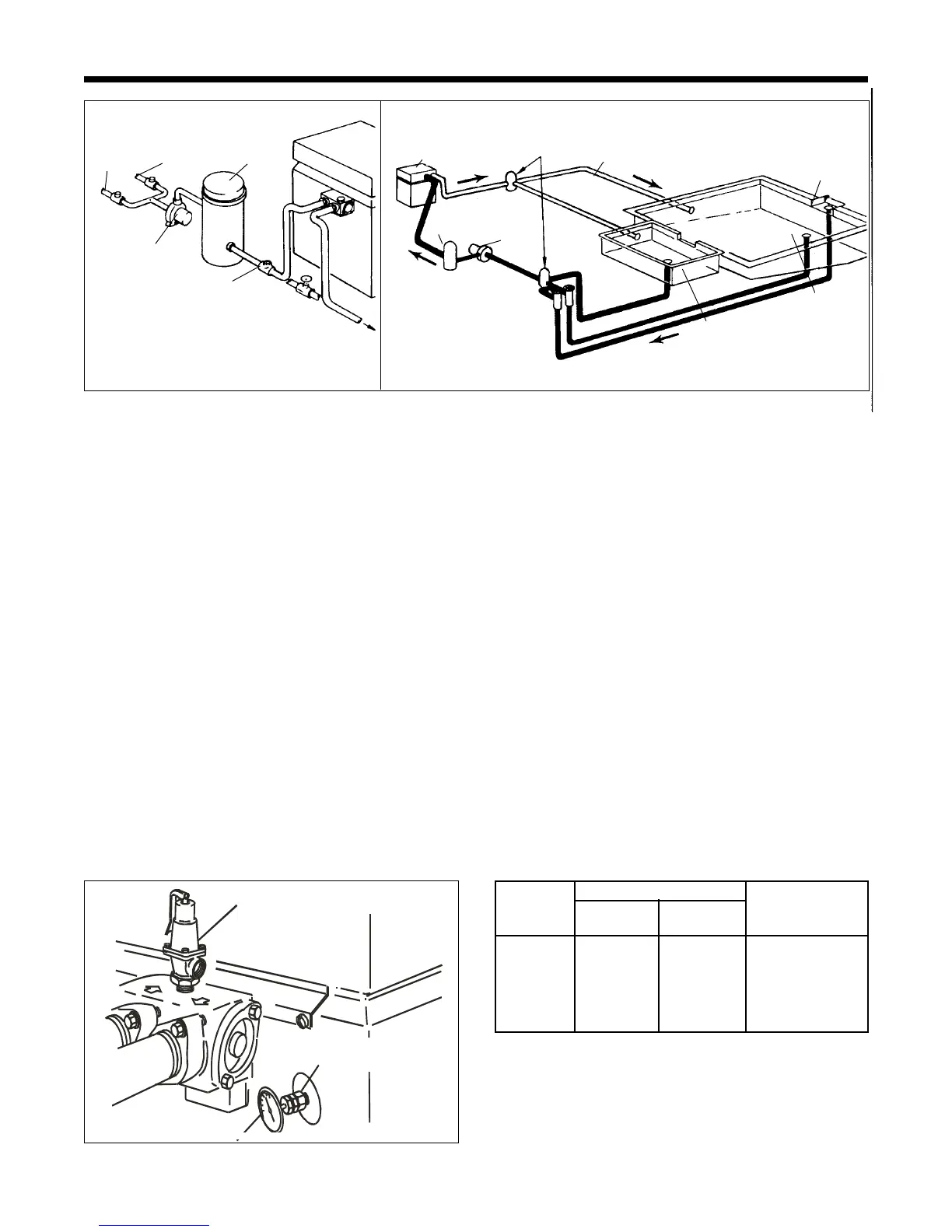
2J. Pressure Relief Valve
A pressure relief valve is not furnished with
the Lite 2 heater. Local plumbing codes may
require it.
To install a pressure relief valve:
1. Remove the 19 mm brass plug on top of the
header and screw in the valve (see Figure 14).
2. The setting of the valve should be at or below
the lowest working pressure of any compo-
nent in the filter system.
2K. Pressure Switch Adjustment
The pressure switch is pre-set at the factory for
normal pool installations. Do not adjust the pressure
switch unless the installation involves special condi-
tions such as:
From
Skimmer
From Main
Drain
Balancing
Valves
Filter
Heater
Pump
Check
Valve
To
Pool
Manual by-pass is used
only when filtration rate
normally exceeds
125 gallons per minute.
Heater
Filter
Pump
Main Pool
Return
Main Pool
Skimmer
Main
Drain
Spa
Balancing valves for
skimmer and drain.
Three-way
changeover
valves
Figure 13. Typical installation.
1. The top of the heater is installed 1 m or more
below the surface of the pool.
2. If any part of the filter system is 1 m or more
above the top of the heater jacket.
NOTE: Do not make the pressure switch
adjustment if the heater is installed more than 4.6 m
below or 1.9 m above the pool surface. Consult
Zodiac Pool Systems, Inc., for recommendations.
On some installations, the piping from the heater
to the pool is very short. The back pressure could be
too low to trigger the pressure switch. If this happens,
it may be necessary to install a directional fitting, or
elbows, where the return line enters the pool. This will
increase back pressure enough for the heater to
operate properly.
2L. Temperature Rise
When the installation is complete, the installer
should then take a temperature rise. Use the figures in
Table 7 to verify proper water flow through the heater.
Figure 14. Thermometer and pressure relief valve
location.
THERMOMETER
(-29°C TO 52°C)
PRESSURE RELIEF
VALVE
An automatic, built-in bypass valve maintains
proper flow through the heater at flow rates less than
7.9 liters per second (l/s). If the system filter-flow
rate exceeds 7.9 l/s, a manual bypass valve is re-
quired. Figure 15 shows a manual bypass valve
installed between the heater inlet and outlet. To set
the bypass valve, follow this procedure:
Temperature Rise Minimum
Minimum Maximum Flow Rate
Size °C °C l/s
125 15 20 1.5
175 18 24 1.5
250 18 24 1.9
325 16 21 2.3
400 17 22 2.3
Table 7. Temperature Rise And Minimum Flow Rates
TEMP AND PRESSURE FITTING
(PETE'S PLUG)