Page 6
sure to push the baffles against the flue collector
sides, closing all gaps.
24. Drill capillary hole (20mm diameter) symmetri-
cally opposite to one on right hand side of jacket.
Remove the grommet from the hole on the right
side of the heater and place it in the new hole.
Re-route capillary and re-install the bracket.
25. Attach the flue collector holddown clamps to the
clips located under the two center header bolts.
26. Replace the gap closures and tighten the screws
securely.
27. Double-check to make sure the wiring is not
pinched against sharp edges, or resting on the
flue collector assembly.
28. Re-install rainshield assembly and replace the
screw securing it to the rear of the jacket.
29. Replace the top assembly. Make sure the tabs
are outside the heater jacket. Fasten the top
assembly with the hex-head screws.
30. Install plastic tie wraps on wiring in the front
compartment (vestibule).
31. Install heater door.
32. Reinstall the flue terminal or draught diverter, if
one was removed.
2D. Site Location
2D-1. Indoor Installation
The Lite 2 LG )heater is designed and certified
for indoor installation only when equipped with a
draught divertor and flue system. Check the literature
or rating plate for the correct LG Lite 2 draught
divertor part numbers. Install the draught divertor
without modification.
WARNING
Improper installation or maintenance can
cause nausea or asphyxiation from carbon
monoxide in flue gases which could result in
severe injury, property damage, or death.
Place the heater in an area where leakage of the
heater or connections will not result in damage to the
area around the heater or to the structure. If this is
not possible, provide a suitable drain pan to catch and
divert any leakage. The pan must not restrict air flow.
16. Re-route the thermostat bulb assembly, then the
pressure switch tube through the hole in the left
side of the vestibule cover.
17. Re-install the temperature sensing bulb in the
header, and fasten it with the retainer bracket
and screw.
18. Re-install the nut, at end of pressure switch line,
into the compression fitting in the header.
19. Route the white wiring beside the heat exchanger
and down to the original location. Be careful to
keep the wires away from the flue collector.
Secure white wires to the pressure switch tube
with tie straps.
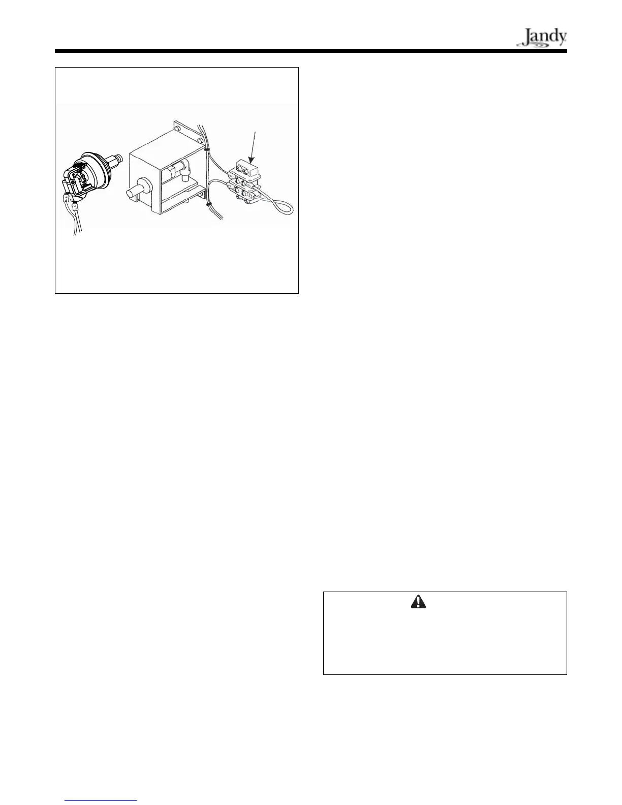
20. Connect the white wire labeled PS to the pres-
sure switch and the other white wire to its
original location at the terminal block (see
Figure 5).
21. Replace jacket/plugs grommets, and re-install the
drain plugs. Tighten securely. Replace the button
plug into the remaining hole in the jacket.
22. Install the flue collector assembly. Be sure the
bottom lips are inside the grooves on the front
and rear combustion chamber panels and are not
pinching any wires.
23. Use the screws removed earlier to replace the
two heat exchanger end baffles. Mount one to
the top of the rear combustion chamber panel
and the other to the top of the front combustion
chamber panel. Before tightening the screws, be
Figure 5. Terminal block.
Terminal
Block