Page 11
ENGLISH
Jandy
®
Variable-Speed Pumps, DV/DVS Models
|
Installation & Operation Manual
Base Configuration
Suction
Side
Height
Pump
Height
1. Pump without Base
7 3/4” 12 3/4”
2. Pump with Base
8 7/8" 13 7/8”
3. Pump with Base
and Spacers
9 1/8” 14 1/8”
4. Pump with Small +
Large Base
10 3/4” 15 3/4”
Table 3. Adjustable Base Dimensions
(VS FloPro
TM
Models Only)
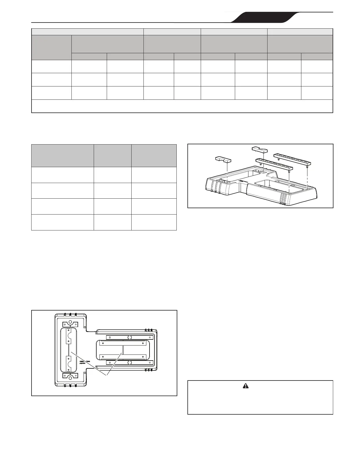
1. Using a hand cutter tool, cut the plastic bars
connecting the top and bottom sets of spacers, as
shown in Figure 6.
2. Push the two top spacers and two bottom spacers
out of the base.
3. Align the pins in the four spacers with the holes in
the base. Snap the spacers into place. See Figure 7.
X
X
Cut
spacers
Figure 6. Cut Sets of Spacers Out of Base
Distance from Sub-Panel 0-50 feet (15 meters) 50-100 feet (15-30 meters) 100-200 feet (30-60 meters)
Pump Model
Inverse - Time Circuit Breaker or
Branch Fuse AMPs
Class: CC, G, H, J, K, RK, or T
Voltage Voltage Voltage
230 VAC 115 VAC 230 VAC 115 VAC 230 VAC 115 VAC 230 VAC 115 VAC
VSFHP130DV
VSFHP130DVS
15A 20A
14 AWG
(2.1mm
2
)
12 AWG
(3.3mm
2
)
12 AWG
(3.3mm
2
)
10 AWG
(5.3mm
2
)
10 AWG
(5.3mm
2
)
6 AWG
(5.3mm
2
)
VSFHP165DV
VSFHP165DVS
20A 30A 12 AWG 10 AWG 12 AWG 8 AWG 10 AWG 6 AWG
VSFHP185DV
VSFHP185DVS
20A 30A 12 AWG 10 AWG 12 AWG 8 AWG 10 AWG 6 AWG
*Assumes three (3) copper conductors in a buried conduit and 3% maximum voltage loss in branch circuit. All National Electrical Code
®
(NEC
®
) and
local codes must be followed. Table shows minimum wire size and branch fuse recommendations for a typical installation per NEC.
Table 2. Minimum Wire Size and Minimum Overcurrent Protection*
Figure 7. Snap Spacers into Place
3.2 Electrical Installation
3.2.1 Voltage Checks
The correct voltage, as specied on the pump data plate,
is necessary for proper performance and long motor
life. Incorrect voltage will decrease the pump’s ability to
perform and could cause overheating, reduce the motor life,
and result in higher electric bills.
It is the responsibility of the electrical installer to provide
data plate operating voltage to the pump by ensuring
proper circuit sizes and wire sizes for this specic
application.
The National Electrical Code
®
(NEC
®
, NFPA-70
®
)
requires all pool pump circuits be protected with a
Ground Fault Interrupter (GFCI). Therefore, it is also
the responsibility of the electrical installer to ensure that
the pump circuit is in compliance with this and all other
applicable requirements of the National Electrical Code
(NEC) and any other applicable installation codes.
CAUTION
Failure to provide data plate voltage (+/- 10%) during
operation will cause the motor to overheat and may void the
warranty.