Page 14
ENGLISH
Jandy
®
Variable-Speed Pumps
|
Installation & Operation Manual
3.5.2 Dip Switch Settings with Automation
Dip Switch 3-4 setting rules are not common across
all Jandy automation systems. Please reference the
following sections to understand the required settings.
For Jandy Aqualink RS Automation System users, a
2022 mid-year update changes the method in which
pumps in this manual interact with Jandy Aqualink RS
systems. Refer to the RS manual for more information.
3.5.3 Pre-2022 Aqualink RS Firmware Rev_V
and Earlier
Aqualink RS systems using rmware Rev V and earlier,
manufactured prior to mid-year 2022, support up to 4
variable-speed pumps. Each pump is assigned an address
of 1 through 4 using Dip Switches 3-4 on the pump. Use
the table below for pump address assignment settings.
These settings are used when connected to the RS485
connection on the pump or when connected to the pump
using a SpeedSet controller’s automation pass-through
wiring connection on the bottom of the controller.
Address Switch 3 Switch 4
Pump 1 OFF OFF
Pump 2 ON OFF
Pump 3 OFF ON
Pump 4 ON ON
Table 4. Local Controller DIP Switch Settings
3.5.4 2022 Aqualink RS Firmware Rev W
and Later
Aqualink RS systems using Rev W and later,
manufactured after mid-year 2022, support up to 16
variable-speed pumps that utilize a pre-assigned PUMP
ADDRESS. Dip Switches 3-4 are not utilized. Pumps in
this manual are all assigned a unique PUMP ADDRESS
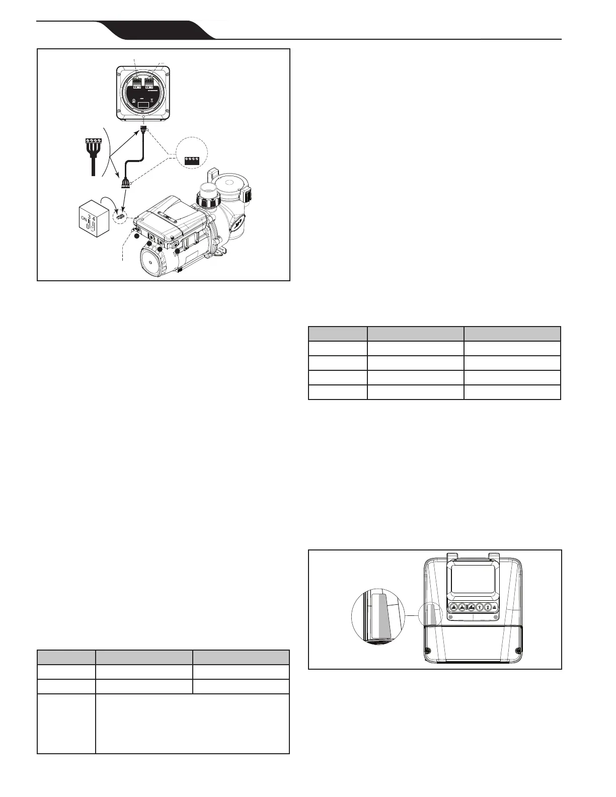
at the factory. The PUMP ADDRESS label can be found
on the pump motor in the location shown below.
PUMP ADDRESS
Figure 10. Pump Address Label Location
When setting up pumps using this method, the pump
address of each pump will initially appear in the
unassigned pump address section of the iAqualink App
or other automation setup device. Utilize the App or
other device to complete pump setup.
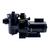
1- 3/8” Threaded
2- 3/4” Threadless
3- 1/2” Threadless
1
2
3
4
2-Position
DIP Switch
Bonding
Lug
RS485
4321
Speedset
Controller
(Bottom View)
BLACK
YELLOW
RED
GREEN
RS485
Cable (22 AWG)
4321
BLACK
YELLOW
RED
GREEN
H0738200_REVB
Conforms to ANSI/UL Std. 1563 Certified to CAN/CSA Std. C22.2 No. 218.1
FOR INDOOR/OUTDOOR USE
POUR USAGE INTÉRIEUR/EXTÉRIEUR
PARA USO INTERIOR/EXTERIOR
10V 200mA
This device complies with part 15 of the FCC Rules. Operation is subject to the following two conditions:
(1) This device may not cause harmful interference, and (2) this device must accept any interference received,
including interference that may cause undesired operation. CAN ICES-003 (B) / NMB-003 (B)
RECOGNIZED
COMPONENT
3032401
Zodiac Pool Systems LLC
Model # SpeedSet
CAUTION/ATTENTION
READ THE INSTRUCTION MANUAL
LIRE LA NOTICE TECHNIQUE
TO AUTOMATION TO PUMP
To Automation
To Pump
Figure 9. Wiring to a Controller
3.4 Pump Controller / Automation
System Setup
Pumps in this manual are compatible with the following
local Jandy controllers and automation systems:
• SpeedSet Controller (local)
• iQPUMP01 (local)
• JEP-R (local)
• All Jandy Automation Systems
Each motor is equipped with an auto-sensing power
circuit which automatically determines if 10v of power
should be supplied to the RS485 wiring in order to
power a local controller interface, or to suppress the 10v
power supply when connected to a Jandy Automation
system.
This auto sensing power circuit eliminates the need for
Dip Switches 1-2 that are present on other Jandy Pumps.
3.5 Dipswitch Settings
3.5.1 Dipswitch Settings with Local
Controller
Please refer to the following table for required settings
for Dip switches 3-4 when the pump is connected to a
local controller.
Controller Switch 3 Switch 4
JEP-R OFF OFF
iQPUMP01 OFF OFF
SpeedSet
Dip Switch 3-4 settings are only important
when connected to a Jandy automation
system using SpeedSet automation pass-
through wiring connection on the bottom of
the controller.
If applicable, please see following sections.
Table 3. Local Controller DIP Switch Settings