Prophi
®
12R / 12 RS
22
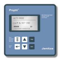
Section 13: Menu INTERFACE
The PROPHI 12 is optionally equipped with a RS485-interface, an internal clock, a
potential free external input (110 … 230 V) and an additional message relay. Therefore
the following functions are only available for version /RS:
1 MESSAGE RELAY [1]
Functions and settings see section 2.3 Error messages (p.7)
2 FAN TEMPERATURE
Input of switching threshold, when message relay = FAN has been selected.
3 EXTERNAL INPUT
The function of the external input (110..230 V) can be selected here: (Not active
if message relay is programmed as “External” or „Remote control“.
[0] - OFF
[1] - 2nd parameter set
Activation of the input in this operation mode releases the 2nd parameter
set featuring the following settings: 19/20 I-transformer; 21 End stop;
22 Control series; 23 Control principle; 24 Output 1st step;
25 Target cos-phi; 26-28 Switching times
[2] - EXTERNAL ERROR
In this operation mode the activation of the input causes a controlled
switch off of all steps (remote switch off)
[3] - Q-OFFSET By activating of the input in this operation mode an additional
capacitive output is switched on independent from target cos-phi and
controlling (value in offset-power programmable).
[4] - Coupling operation parallel – Coupling operation of two systems, the input
receives a signal of the coupling switch between the systems, the systems
symmetrically (parallel) switch on the steps.
[5] - Coupling operation serial – Coupling operation of two systems, the input
receives the signal of the coupling switch between the systems, the
systems sequentially switch in the steps (first system 1, then system 2)
[6] [INPUT FIXED STEP]
4 OFFSET POWER (Fixed power step) – only if external input on Q-OFFSET!
Input of reactive power value that is added when activating the input to the
required reactive power.
5 ... 9 Adjusting of internal CLOCK (HOUR, MINUTE, DATE)
10 PROTOCOL COM1
-----
MODBUS KTR
MODBUS RTU Modbus-protocol for individual usage
ASCII OUT Transmitting of grid-values as ASCII-Data,
permanent sequential output of:
U, I, Q, P, S, switched steps
(display ”XXX---------” = 3 active steps)
MASTER MMI Adjustment
in case of real current measurement
with MMI6000/7000 (s. application p. 29)
EXTERNAL Usage of an external measuring device (MMI6000/MMI7000).
The values of this device are used for display and controlling.
SLAVE MODE Coupling of several controllers via interface (s. page 28)
MASTER MODE see above