Do you have a question about the janitza Prophi and is the answer not in the manual?
Overview of various measured values displayed by the Prophi controller.
Summary of configurable parameters and their setting ranges.
Covers ambient conditions, inputs/outputs, measurement accuracy, and device views.
Guidance on proper transport, mounting, usage, and maintenance for safe operation.
Explanation of warning symbols used in the manual for electrical safety.
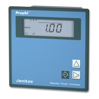
Details on the Prophi controller's purpose, features, and electrical quantities measured.
Covers maintenance, repair, calibration, foil cleaning, waste disposal, and data protection.
Details on electrical quantities measured, calculated, and information indicated by the Prophi controller.
Explains how capacitor stages are switched and the function of switching outputs and net return.
Instructions for mounting the Prophi controller and connecting measurement and supply voltage.
Details on how to connect using sum current transformers and necessary programming.
Instructions for connecting current measurement via Amperemeter or current transformers.
Guides on setting the current transformer ratio and checking current measurement accuracy.
Explains the indication of real power, including possible errors and connection checks.
Details on configuring relay and transistor outputs for capacitor stage switching.
Common errors and their causes related to switching outputs not functioning correctly.
How to set and changeover between target-cos(phi) values for power factor control.
Description of the alarm relay function, events, and how to check alarm output status.
Details on Modbus/Profibus protocols, bus structure, shielding, and cable specifications for RS485.
Lists common error descriptions, possible causes, and recommended remedies for Prophi controller issues.
Information required for support and contact details for Janitza electronics GmbH.
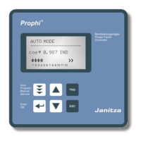
Explains how to navigate between operating modes and the functions available in Automatic and Manual modes.
Illustrates how to change modes and perform programming actions using the device keys.
Details on setting target-cos(phi) values in standard programming for power factor correction.
Instructions on how to set the current transformer ratio correctly for accurate measurements.
Guide to using the 'learn' function to automatically detect and save configuration settings.
How to program the power of individual capacitor stages for optimal compensation.
Configuring the ratio between capacitor stages for step-by-step compensation control.
Instructions for programming the number and type of switching outputs (relay/transistor).
Procedure for deleting saved peak and lowest measured values from the controller.
Setting capacitor stages to be fixed (non-controlled) in automatic mode.
Setting the discharge time for capacitor stages after switching or power return.
Defining the pause time between capacitor stage connections to prevent rapid switching.
Configuring the controller for power station service to manage behavior with low or no current.
Setting the choke degree for compensation systems to optimize capacitor current and switching order.
How to configure the voltage transformer ratio (number 1 and number 2) for accurate voltage measurement.
Configuring harmonic thresholds to protect capacitors and avoid frequent switching.
Setting the switching frequency for transistor outputs, noting potential impact on serial interface.
Details on configuring alarm output, assigning events, and acknowledging alarms.
Configuration and thresholds for voltage, current, and capacitor output alarms.
Settings for alarms related to real power supply, harmonics, and overtemperature.
Setting the averaging time for calculating the mean value of cos(phi).
Configuring the averaging time for summarizing reactive power measurements.
Setting temperature limits and assigning a switching output for ventilator control.
Example of programming the lower temperature limit for ventilation control.
Demonstrates assigning a specific output to the ventilator control function.
Configuring upper/lower temperature limits and pause time for overtemperature disconnection.
Choosing between displaying actual cos(phi) or actual real power in manual mode.
Instructions for programming, entering, and changing the device password to protect settings.
Adjusting the display contrast for optimal readability.
Procedure for resetting the programming to manufacturer defaults, requiring a password.
Configuring the correction angle for phase shift between current and voltage.
Information on the device's software version and its unique serial number.
Setting the device address and selecting the transmission protocol (Modbus/Profibus) for serial communication.
Configuration of baud rate for Modbus RTU and details on Profibus DP V0 compatibility.
Details on how measured values like cos(phi), current, power, and stage status are displayed.
Shows the display of parameters like Target-cos(phi), CT ratio, and stage power in standard programming.
Illustrates display of settings like Fix stages, Discharge time, and Alarm messages in expanded programming.
Summary of configurable parameters and their setting ranges in standard programming.
Summary of configurable parameters and their setting ranges in expanded programming.
Detailed technical data including weight, ambient conditions, operating parameters, and safety guidelines.
Specifications for measurement accuracy, inputs, outputs, switching capabilities, and life expectancy.
Illustrations of the device's back side, side view, and overall dimensions, including RS485 interface option.
Brief guide to learning configuration settings for target-cos(phi) and current transformer ratio.
Summary of programming steps for stage power, stage ratio, and number of stages.
| Frequency Range | 50 / 60 Hz |
|---|---|
| Operating Temperature | -10°C to +55°C |
| Storage Temperature | -20°C to +70°C |
| Humidity | ≤ 95% (non-condensing) |
| Protection Class | IP20 |
| Communication Interface | RS-485, Modbus RTU |
| Measurement Parameters | Voltage, Current, Power, Energy, Frequency, Harmonics |