Page 10
Reactive Power Controller
= Key 1 = Key 2 = Key 3
Installation and putting into service
Measurement and supply voltage
The controller Prophi can be delivered in two connec-
tion varieties for the measurement and supply voltage.
In the version measurement L-L, the measurement and
supply voltage must be taken from two outer conduc-
tors. In version measurement L-N, the measurement
and supply voltage must be taken between outer con-
ductor L and neutral N.
Before connection, please ensure, that the local net con-
ditions match the data on type plate. The range of the
measurement and supply voltage is given by the type
plate and is connected via a fuse (2…10A, time lag type)
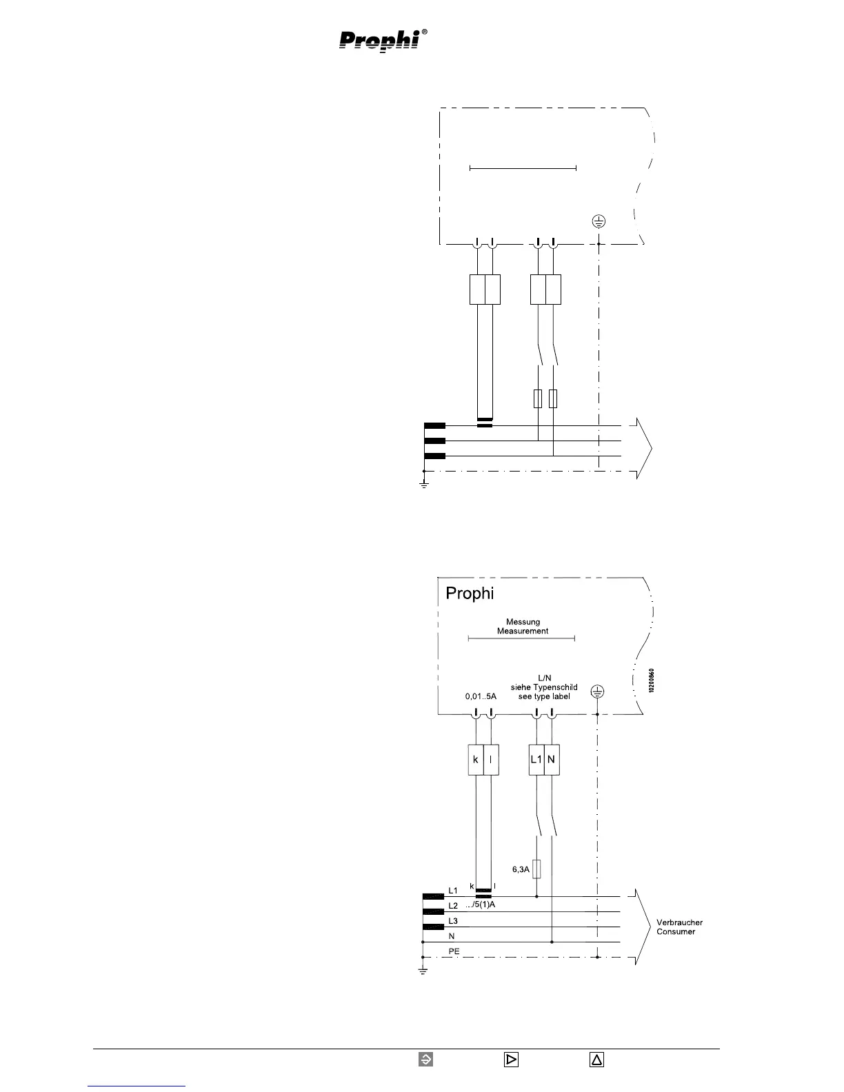
Diagr.: Connection of measurement and supply voltage
(L2-L3) and current transformer.
c
c
Prophi
Messung
Measurement
0,01 .. 5A
L/L
siehe Typenschild
see type label
../5(1)A
L1
L2
L3
PE
k l
2 .. 10A
Verbraucher
Consumer
kl L2L3
Diagr.: Connection of measurement and supply voltage
(L1-N) and current transformer.
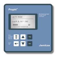
If the measurement and supply voltage is within the
allowed range, Prophi indicates the voltage on the ter-
minal.
While measuring via voltage transformers, the voltage
transformer ratio must be programmed.
Attention!
The measurement and supply voltage must
come from the low voltage net, which is su-
pervised.
The connected measurement and supply voltage may
not exceed the voltage, mentioned on type plate for
more than 10% or underscore for more than 15%.
To ensure, that the connected measurement and supply
voltage is within the allowed range, please check the
voltage at the terminal with a voltmeter.
Attention!
Voltage, which is out of the indicated range
on type plate can destroy the instrument.
c
Attention!
The operating voltage for the contactors should
be received from an outer conductor connected
to the controller.