Prophi
®
12R / 12 RS
6
Section 2 Installation and connection of the controller
The device is designed to be incorporated into the front panel of a PFC-cabinet. It requires
a switchboard section of 138 x 138 mm to DIN 43700/ IEC 61554. The controller is
inserted from the front and is attached by means of the appended clamps. The
controller may be inserted only by qualified technicians and must be operated in
accordance with the specified safety regulations.
Before the device is connected up, all leads and cables must be checked to ensure that no
current is flowing through them and the current converter must be short-circuited. Care
should be taken to ensure that the measuring voltage and current are in the correct phase
2
position. The measuring-current circuit must be wired with copper leads of 2.5mm . The
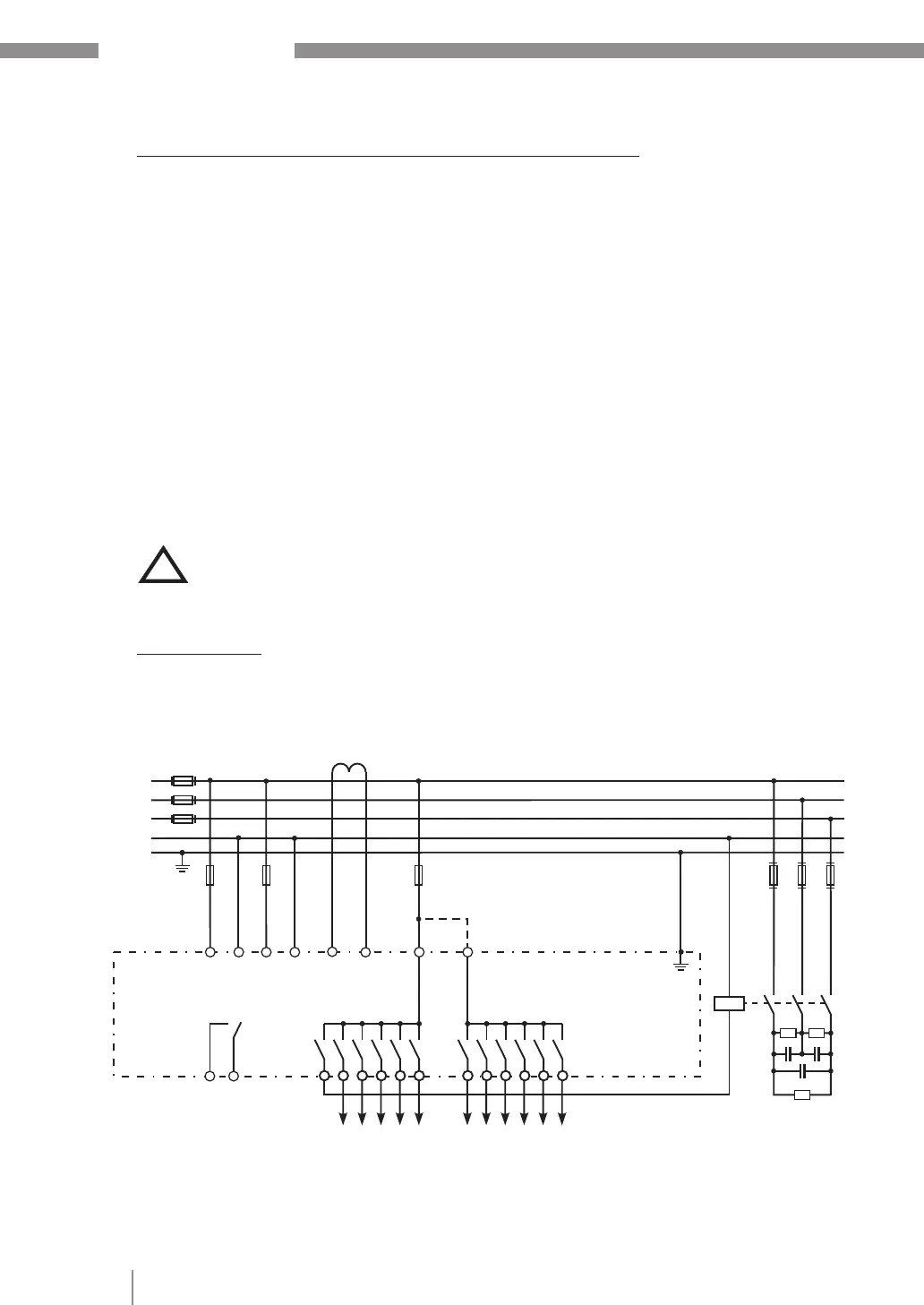
connection should be set up as shown below. The specified safety regulations must be
observed.
The measuring voltage may lie in the range from 30...440 V~ (L-N) resp. 50..760V~ (L-L)
(programming of phase correction needed)
The operating voltage is 110...440 VAC +/- 10%.
The coil voltage for the capacitor contactors and the measuring voltage
must be drawn from the same phase conductor, as only the measuring
voltage is monitored. (Protection against direct reconnection of the
capacitor contactors in the event of momentary single-phase power
failure)
Connection plan
L1 ( R)
L2 ( S)
L3 ( T)
N
me as.cur rent
Im ( 5A/1A)
1. c apacit or
br anc
su pply
vo ltage
Vb
me as.
vo ltage
Vm
k l
P1 P 2
1 2 3 4 5 6 7 8 9 10 11 12
ca pacitor
co ntactors 1-6
al arm
re lay
ca pacitor
co ntactor s 7-12
power factor
co ntroller
T 6,3 A
T 2A
T 2A
PE
K1
a b
Ub Um Im
(L) (N) L1 N k l
(L3) (L2)
Power feed Load side
!