Prophi
®
12R / 12 RS
23
1 2
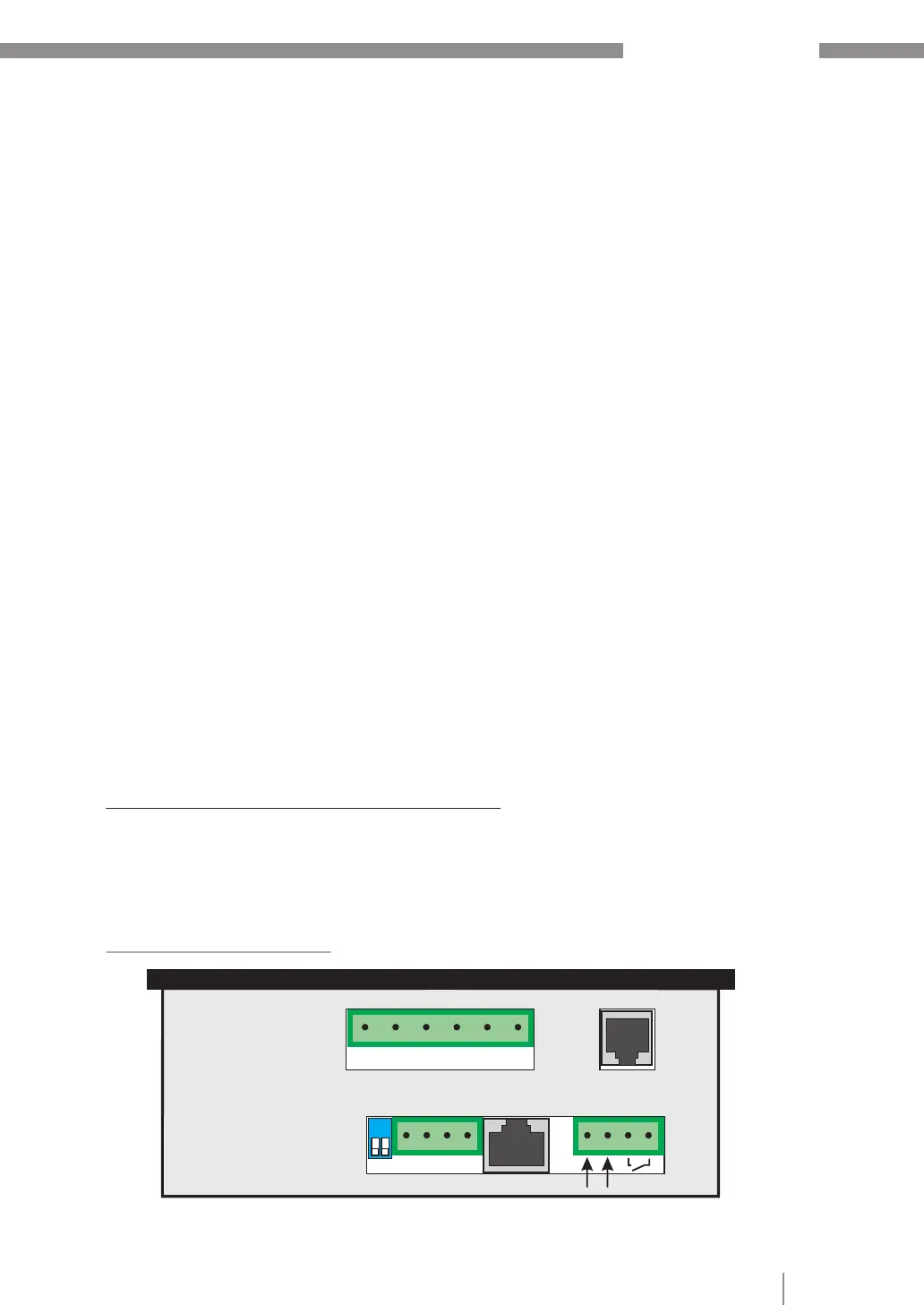
EXT. IN-/ OUTPUT
INTERFACE RS 485On
SERVICE
Gnd B A PE
ext. input
110...230V
message-
relay
Switch for
terminating resistor
Vb Vm Im
L N L1 N k l
(L3) (L2)
Depending on the selected protocol the following settings may be partially deactivated:
11 BAUDRATE COM1 Baudrate 9600...256000 adjustable
Parity NONE, ODD, EVEN selectable
12 ADRESS COM1 [1] (1...255)
13 Number MMI [1] (1...9) Number of connected MMI
14 Type of measuring device (MMI6000 / MMI7000 / MMI8003 / UCM-5)
15 Number of BR7000-1 (1...4) Connected devices during cascading
16 ASCII transmit. interval [10] sec. (1-255) Repeat. time ASCII transmission
17 Separator (for ASCII ) Selection HT; LF/CR; SP; CR/LF; Minus; CSV
An optional hardware-adapter „IF8000" extend the device with a 2nd interface COM2:
18 PROTOCOL COM2 ---- OFF
MODBUS KTR Modbus monitoring
MODBUS RTU Modbus standard protocol
SYNC-MODE compare separate application
EXTERN
TI8004 temperature interface
19 BAUDRATE COM2 compare COM1
20 ADRESS COM2 compare COM1
21 Type of measuring device compare COM1
22 FUNCTION TI8004 system-, unit- or step monitoring
23 Number of sensors [4] (1...12) compare application Ti8004
24 - 36 correlation step <--> sensor
Instructions for bus wiring when using the interface
R For bus wiring screened cable has to be used!
R The bus wirings (incoming and outgoing leads) always have to be applied directly to
the device (no branch boxes)!
R In the devices at the end of the busses the terminating resistors integrated in the
device have to be activated (DIP-switch ON).
Connecting plan INTERFACE: