Do you have a question about the janitza UMG 512 and is the answer not in the manual?
Explains the pictograms used in the manual for warnings and notes.
Provides essential guidelines for safe and proper operation of the device.
Details the necessary checks to ensure faultless and safe operation upon receiving the device.
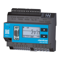
Lists the components included in the standard delivery of the UMG 512.
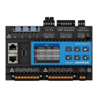
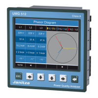
Outlines the key technical specifications and capabilities of the UMG 512 device.
Describes how the UMG 512 continuously measures and calculates effective values.
Specifies requirements for device placement and mounting for optimal ventilation.
Details the procedure for connecting the protective conductor to the device.
Explains how to connect the necessary supply voltage for device operation.
Illustrates connection diagrams for voltage measurement in different network types.
Defines the function of each key on the device for navigation and control.
Explains how to navigate and select between main values and by-values.
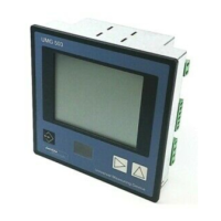
Describes the initial display upon device startup showing key measurements.
Guides users on switching between different measurement value displays.
Prerequisites for configuring the device, requiring a connected supply voltage.
Overview of the menu structure for device settings and language selection.
Configuration options for Ethernet (TCP/IP) and RS485 interfaces.
Settings for baseline and supporting measurements, including transducers.
Provides details on device dimensions, weight, battery, and environmental conditions.
Details the electrical specifications for the device's power supply.
Lists the technical parameters and ranges for voltage measurement inputs.
Details the available measurement functions, their precision classes, and ranges.
Lists common faults, their causes, and recommended remedies for resolution.
| Device Type | Power Quality Analyzer |
|---|---|
| Memory | Internal memory for data logging |
| Power Measurement | Active, Reactive, Apparent |
| Frequency Range | 45 to 65 Hz |
| Communication Interfaces | Ethernet, RS485 |
| Protocols | Modbus TCP, Modbus RTU |
| Display | Graphic LCD |
| Operating Temperature | -10°C to +55°C |
| Dimensions | 96 x 96 x 100 mm |